1987 Pursuit Center Console
225 Yamaha
Hynautic Hydraulic Helm H-50 Rebuild
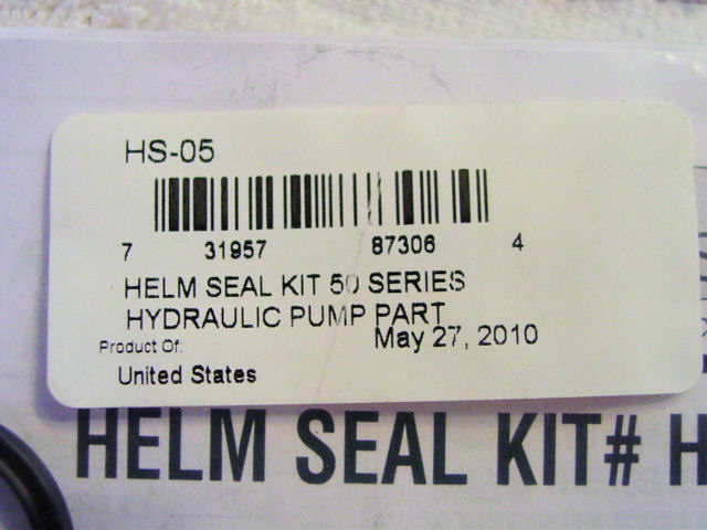
Helm Seal Kit # HS-05
Hopefully this write up will help anyone who would like to rebuild their helm themselves.
Mine started leaking intermediately at the top of the helm. I ordered a Seal Kit from Jamestown Distributers for $37.59 total. The kits came with instructions and Air Purge Instructions which was great.
I took my helm completely apart while waiting for the kit to come in. That way I could clean and paint the parts for a total rebuild back to brand new.
|
|
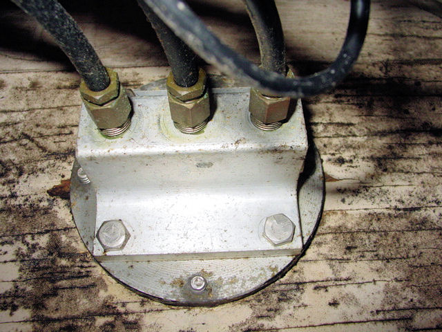
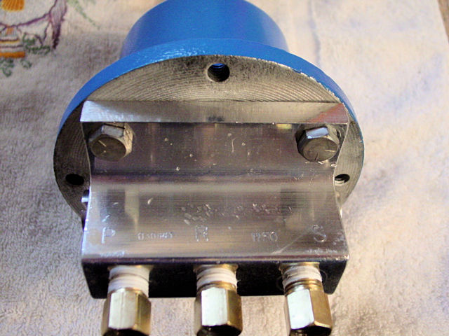
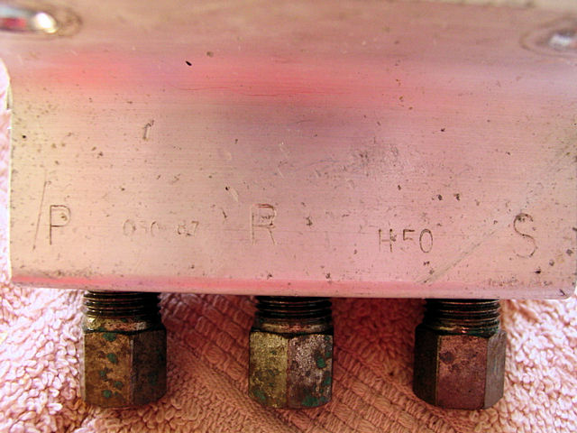 Note the letters P, R, S stamped into block. Make sure you mark the lines before removing them with these letter. I used blue painters tape. Also you will notice the H50 stamp which is what the Helm is. |
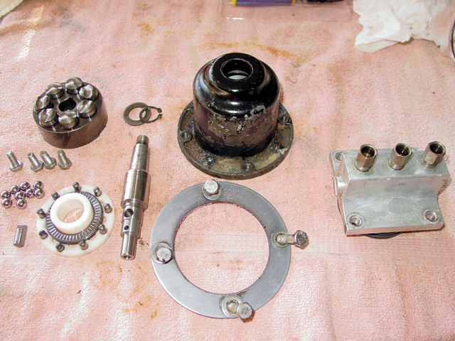 Disassembled Make sure you do not let any of the bearings get away from you. They fall out fairly easy. |
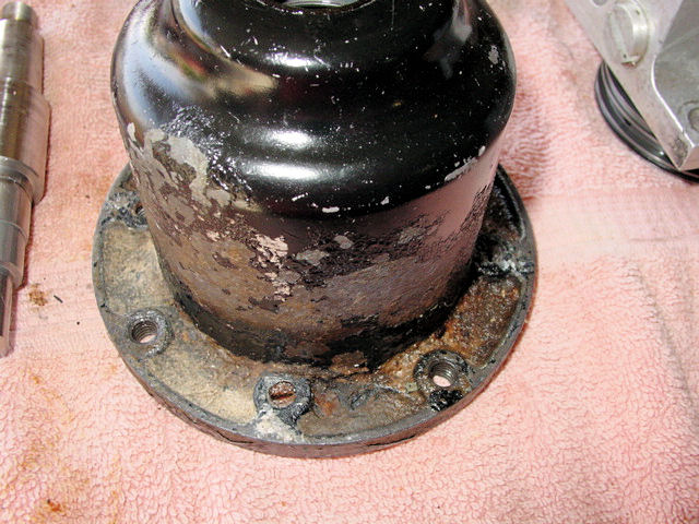 Lots of gunk buildup over the years |
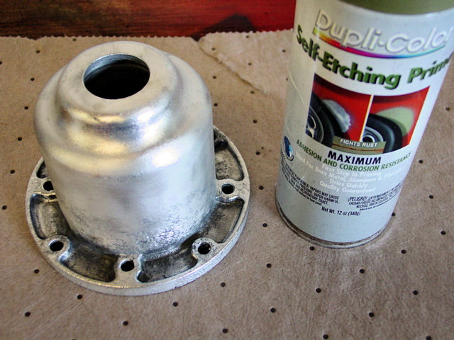 Once cleaned and ready to prime, I used Self-Etching Primer for aluminum |
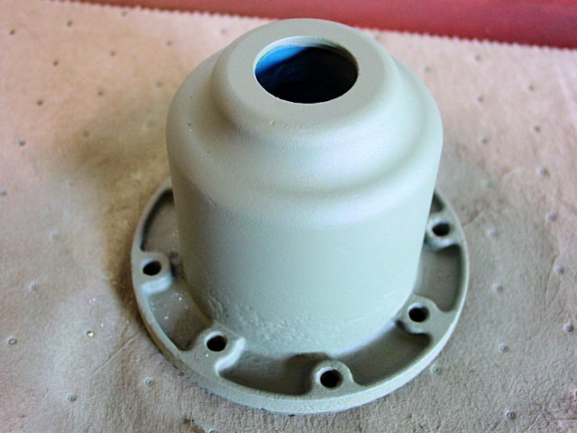 I taped off the bottom and the inside and primed |
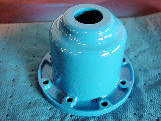 Then I shot it blue to match the theme of the boat which is sail blue and not the baby blue that it looks like in the pic. |
 The kit |
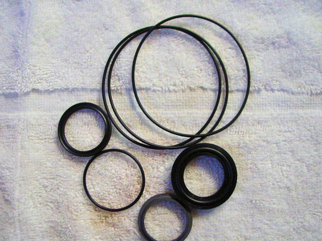 The gaskets, which some were not used for my Helm |
 The bottom two gaskets were not needed for my Helm. A note in the instructions reads: All helms produced after February 1985 use a single seal #224015 (item 21) in place of item 4 and item 8 shown in drawing. This seal is incorporated in the Seal Kit #HS-05. The top seal in the pic is seal #224015 |
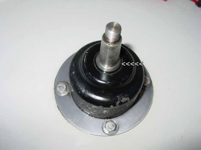
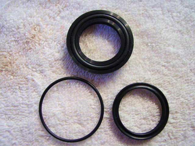
 I used a 15/16 socket and extension to push in the first seal. #700068 Wiper Seal. The smaller end of it goes towards the top of the helm. It is pictured above and is the grayish seal below the others. It is a hard plastic. |
 The next seal is the one with an O-ring inside it, which is the #224015 (item 21) pictured above with the 2 you discard if not needed. |
 This piece then goes in and the knobs align and go into the holes shown on the left. Be careful as the flat washer shown, along with the bearing and another washer can fall off. So I installed it while holding the helm sideways, then rotated it until the knobs fell into place. Underneath the two flat washers and flat bearing is another O-ring (#8) that needs to be replaced. On the drawing, it is 8, 7, 6, 5 from bottom to top. Like the instructions show, the "thick" bearing (#7) goes on the bottom. |
 Once in place, it is time to install the shaft |
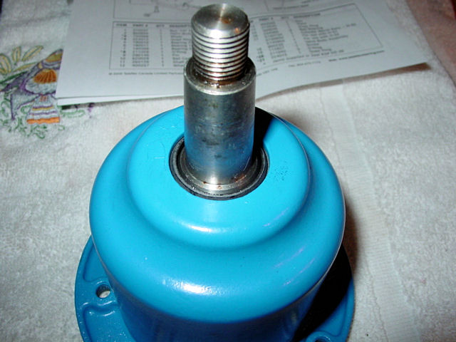 It was easier to istall from the top of the helm, instead of from underneath. Just push into place until it looks like this. |
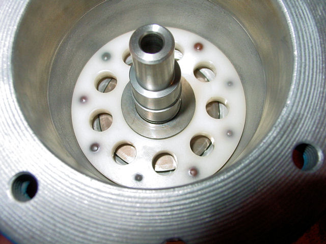 Then drop the flat washer (#14) down over it. You can see the groove down by the flat washer where the snap ring goes. |
 You can get a cheap snap ring plier kit from Lowes. I paid about 14 bucks for this one and it came with 3 inter-changable heads. Snap the O-ring into the groove. |
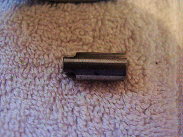 This piece (#13) goes into the hole on the shaft |
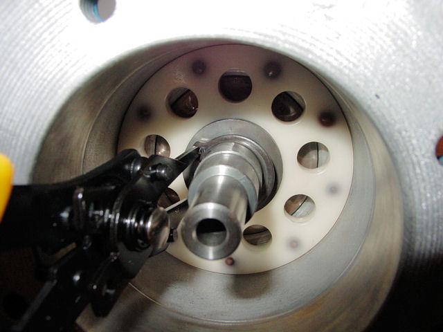
 This part can get tricky and patience is needed. You need to line the flat part up and down as it needs to fit into the groove of the next piece (#17), Cylinder Barrel. I used the needle nose pliers to slide it in place as my fingers would not fit to do it. |
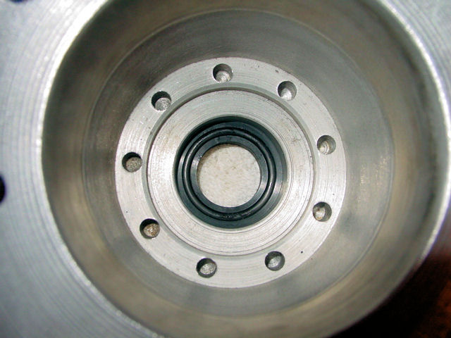
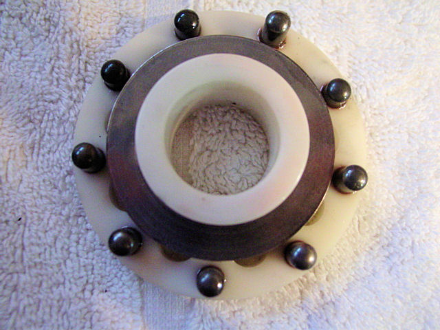
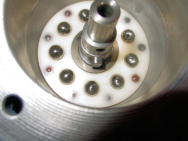 Now you can install all the bearings. They do snap into place somehwhat, but be careful as they can pop out. Notice the alignment of piece #13 from above? It needs to fit into one of the grooves in the next pic. |
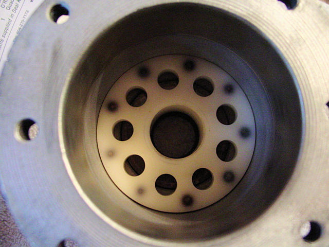
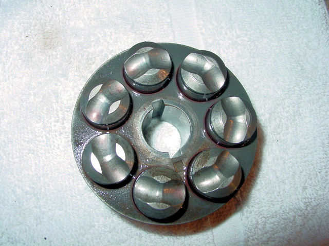 These need to be aligned as shown above, in a circle for the bearings to rest on once installed. Once they are pushed into place they should not fall out. Each one has a spring under them, so once in place inside the helm, you will be able to push it down and it will spring back up. |
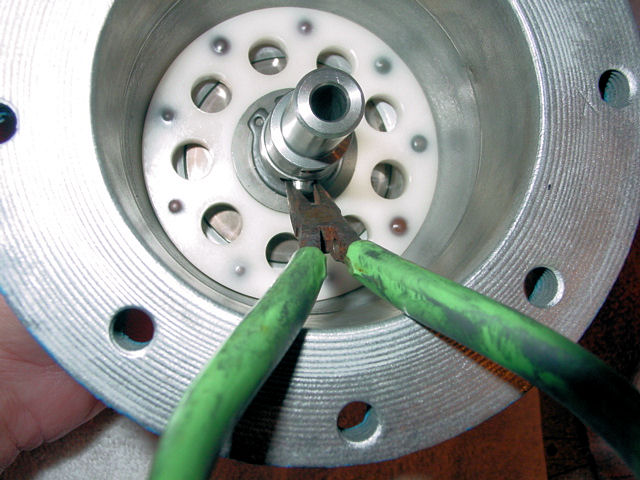
 As I said, installing this part can be tricky as the piece #13 will turn on you. So take your time to slide this part down in the helm until you can see #13 in place. Once in place, you should be able to turn the shaft and this piece will turn with it, plus push in down freely and it should come back up freely. |
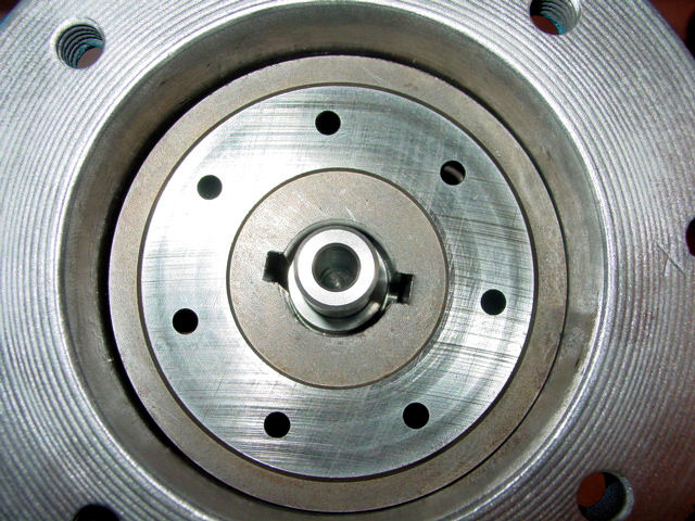
 Valve Body Assembly with the three new O'Rings (#20) 211040 installed |
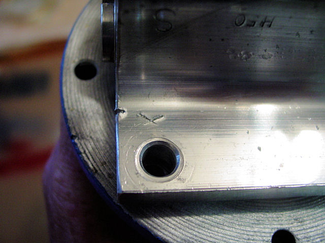 The X shown right above the bolt hole is one of the Timing Alignment Marks, referred to in the NOTICE on the instructions. It is very important you follow the aligment NOTICE. |
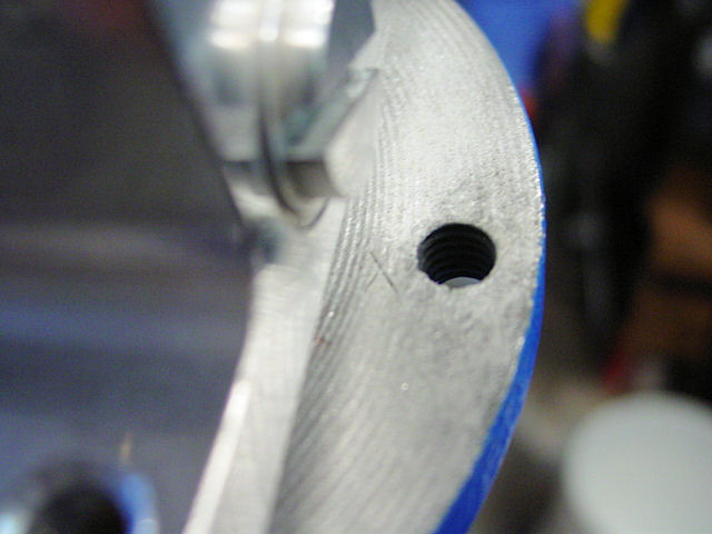 The other X stamped on the helm right next to the bolt hole. |
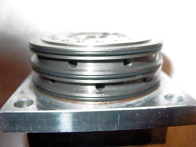
 The block bolted back in place. Be careful when installing the block so as not to break any of the 3 O'Rings on it. I used a little oil to lube them up so they would slide in easier. Then I tighted the bolts a little at a time, like on a rim of a vehicle. This way you can suck the peices together evenly. |
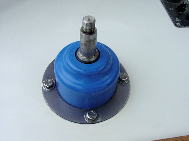 Here is the helm installed on the boat again. |
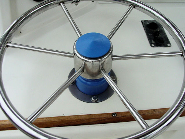 Then with the wheel back on |