|
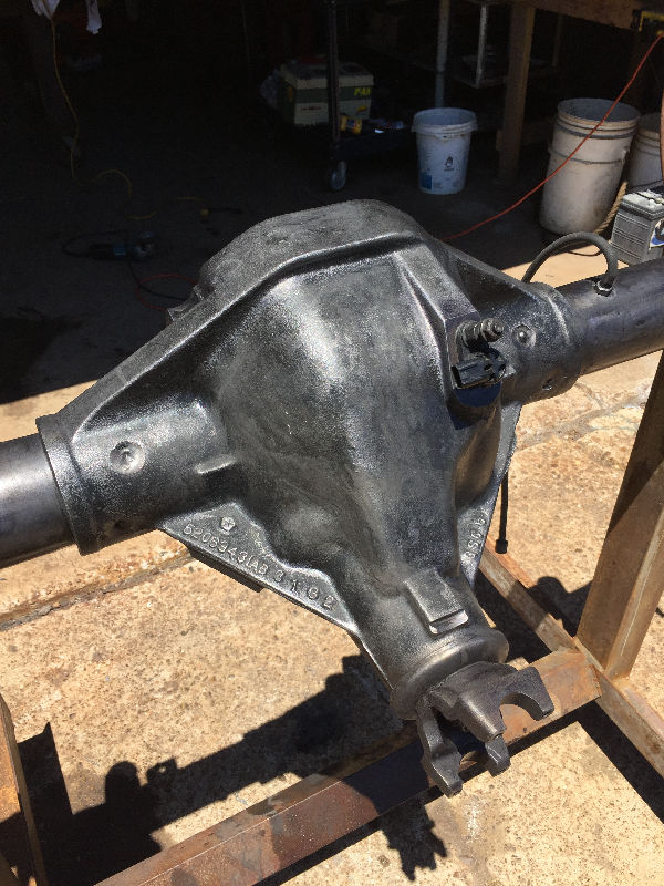
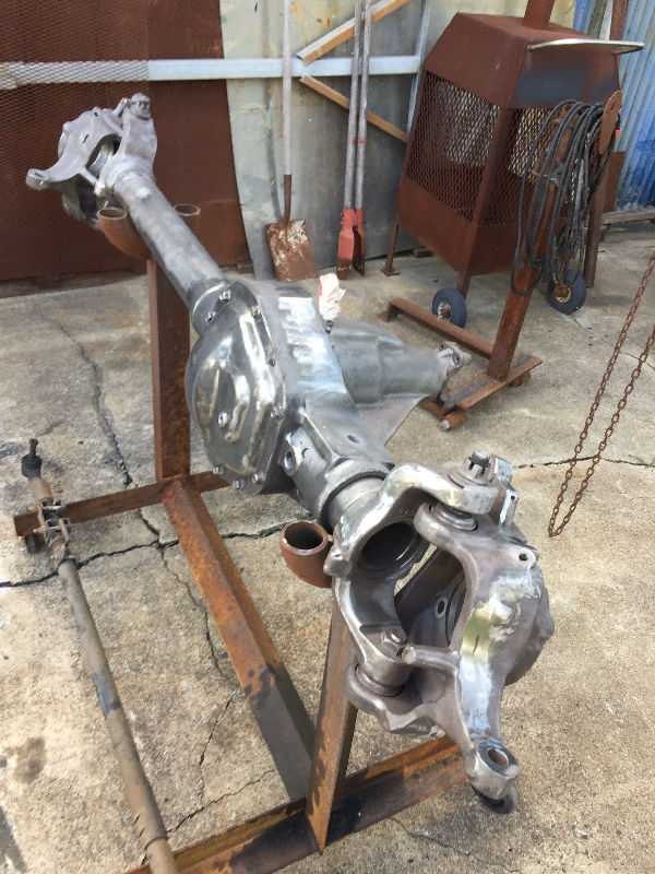
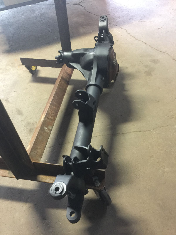
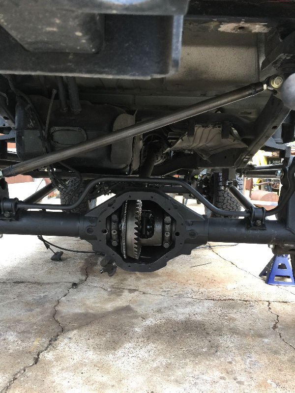
 Build date and gear ratio, the gears were changed out to 4.56 to match the rear axle |
 It was tore down, cleaned up and rebuilt |
 I also cleaned up all the casting marks with a Tiger Paw, basically any rough edges |
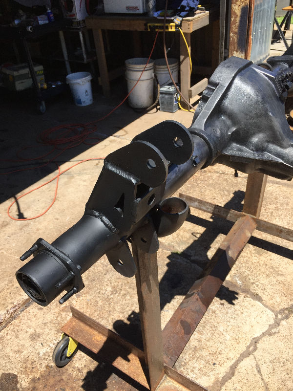
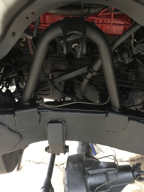
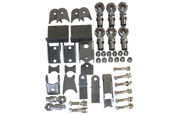 This is the front heavy duty link kit |
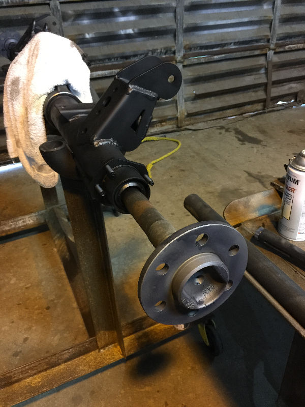
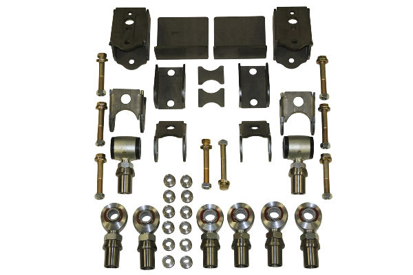 The rear heavy duty link kit |
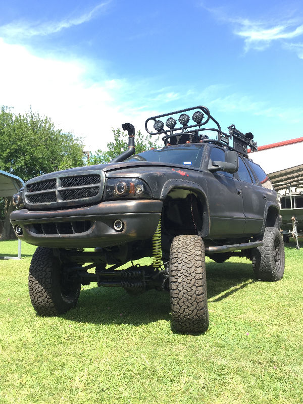
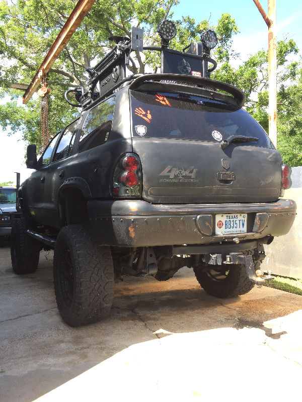
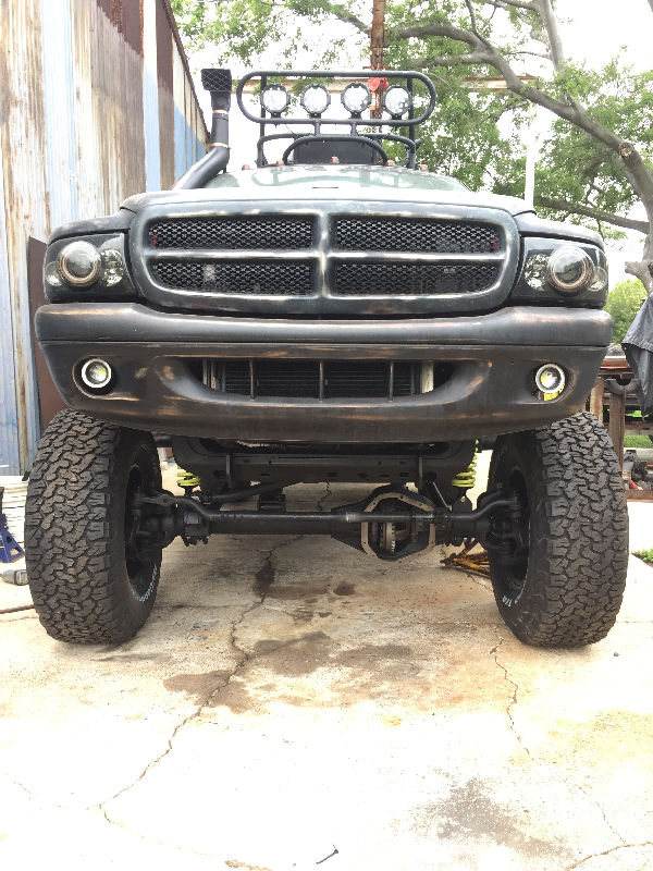
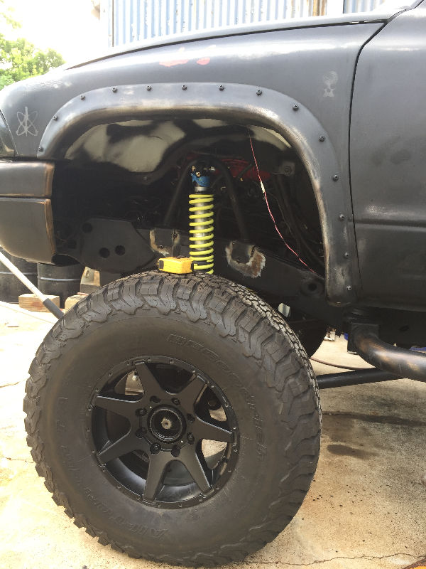
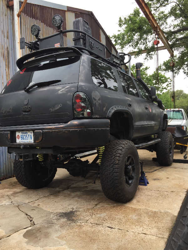
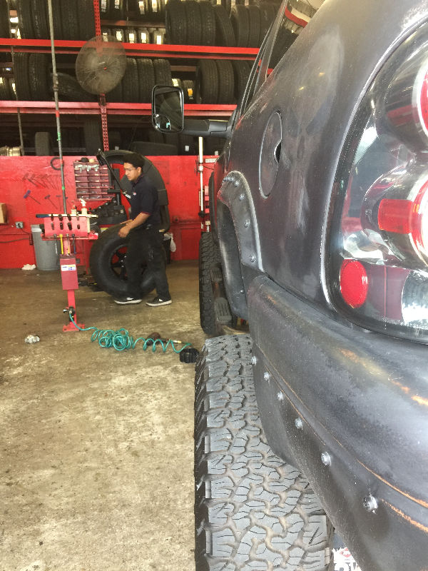
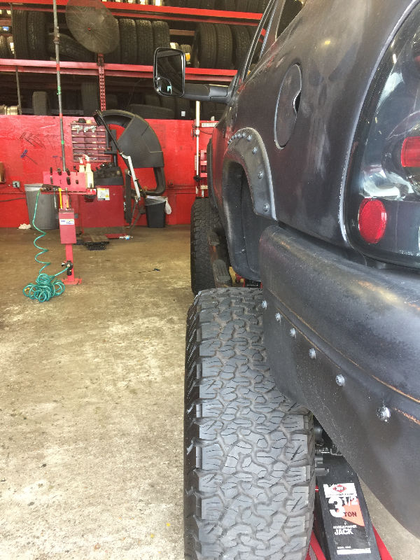
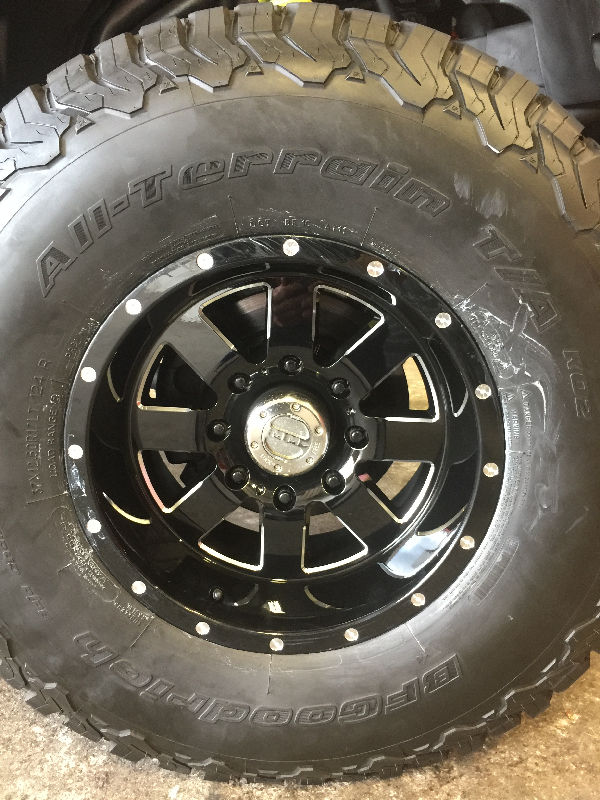
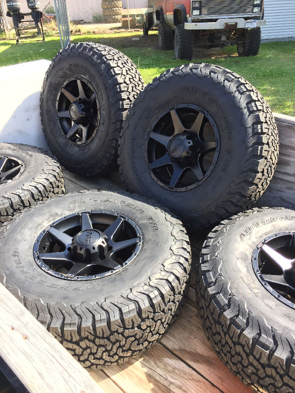 37" BFG KO2's with the wrong rims. These rims are Ultra 205 Tempest 17 x 9's. They have zero offset, which didn't give me the clearance I needed. After the build, I returned the rims for a full refund and got the right rims. I ordered 5 and we are now fabricating a rear tire carrier. |
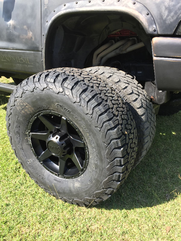 Next to the 35's I was running |
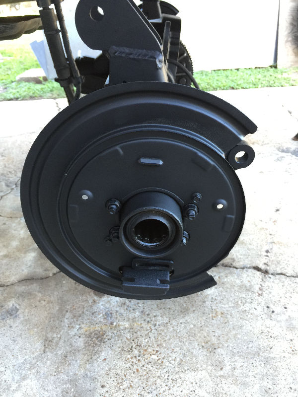
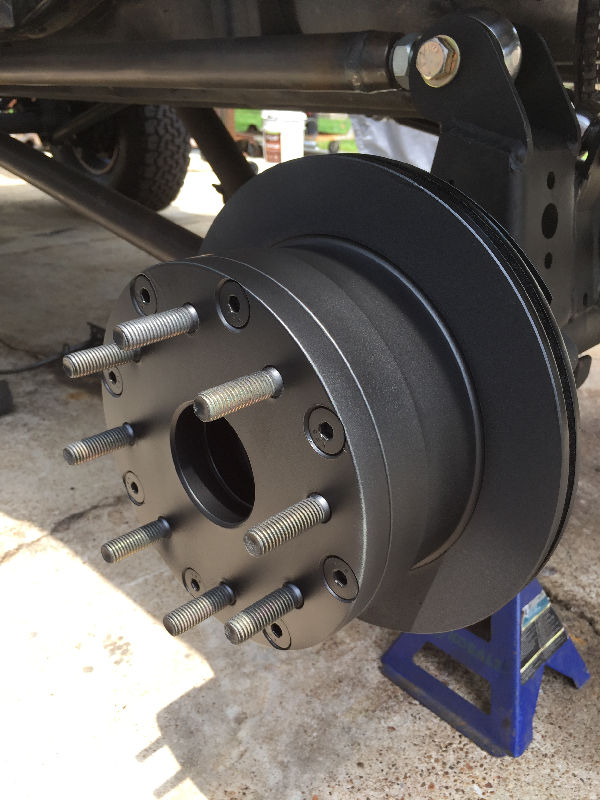
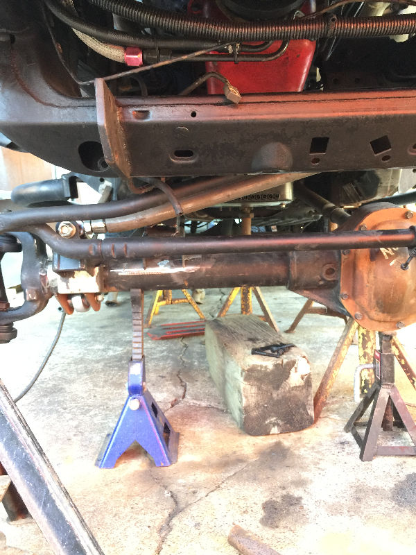
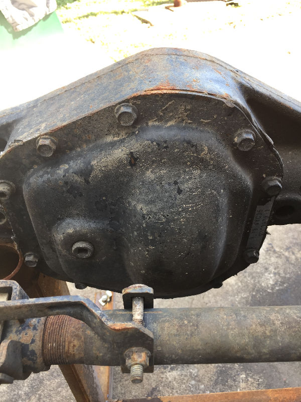
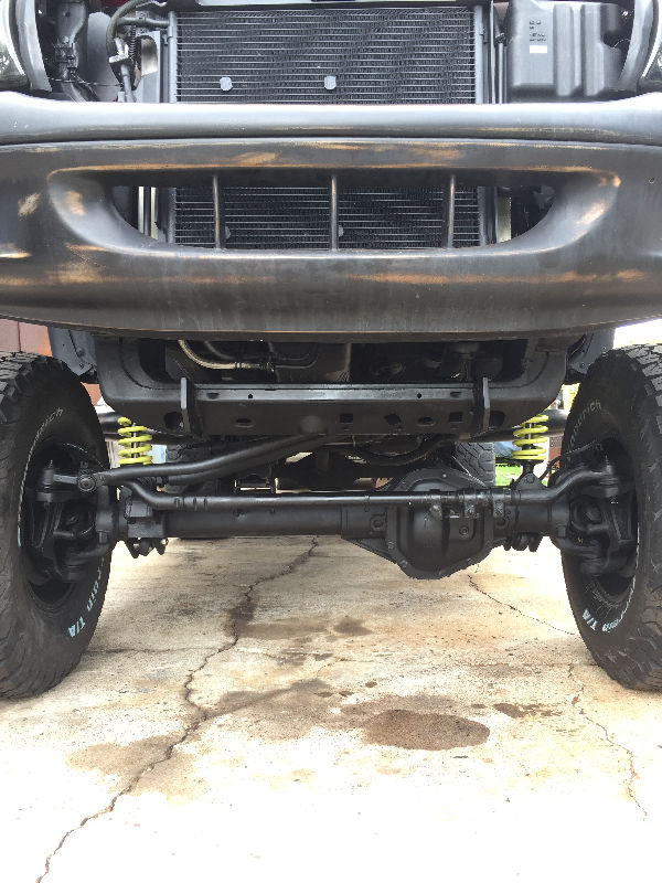
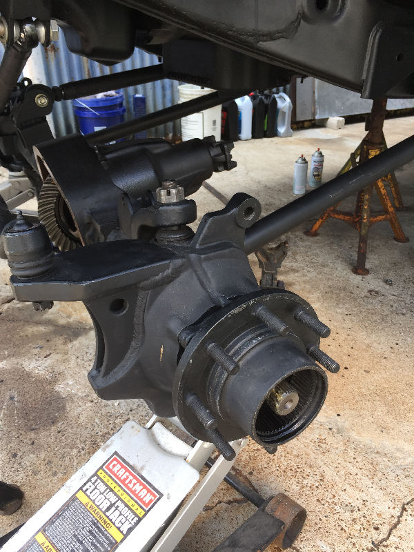
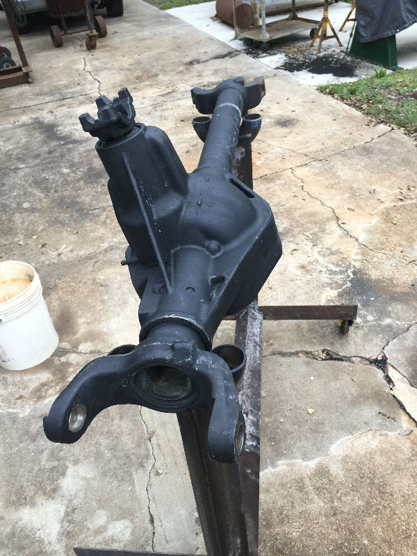 Painted axle housing |
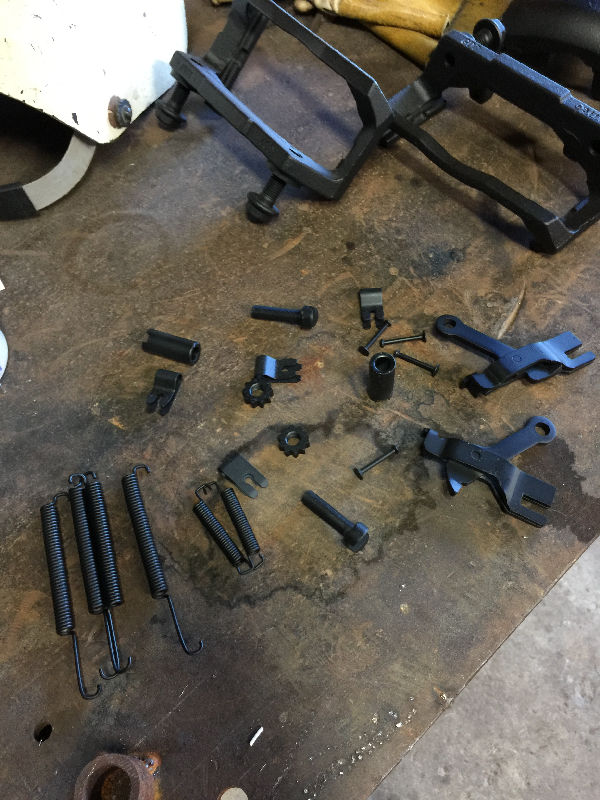
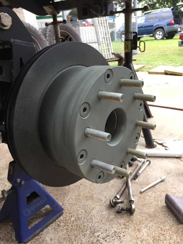
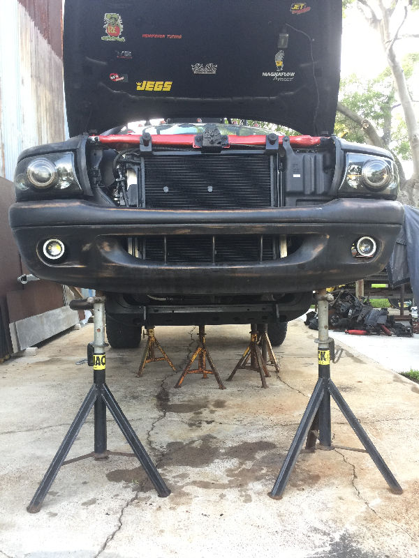
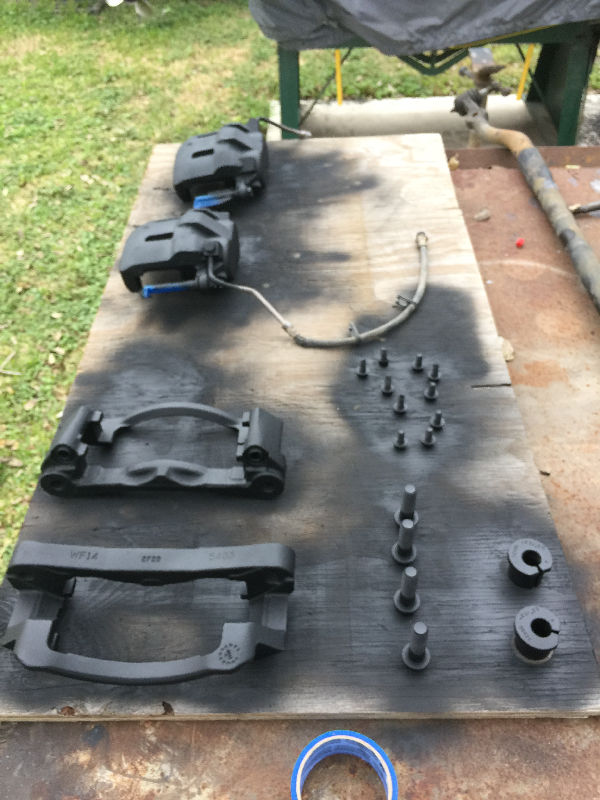 I wanted this to be a clean build. So either parts were sandblasted and painted or replaced with new. |
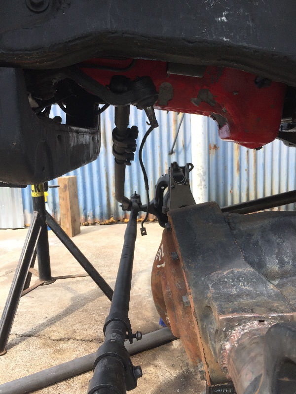
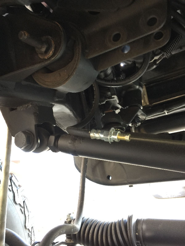
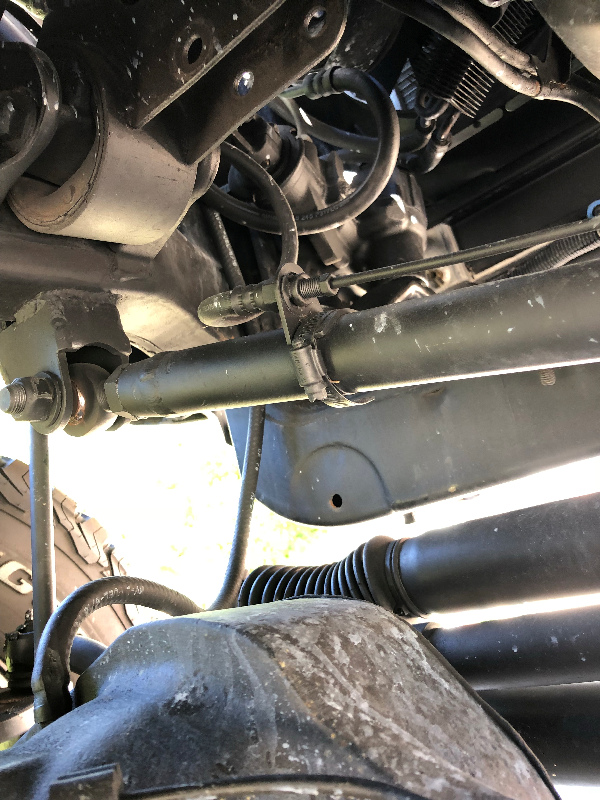
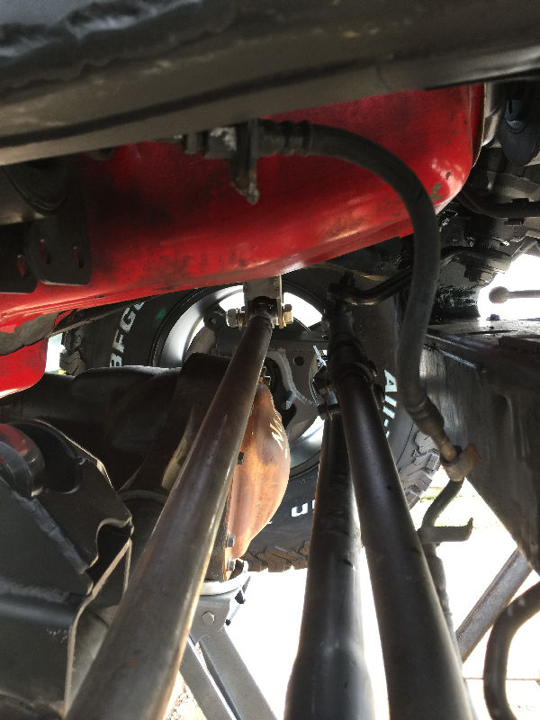
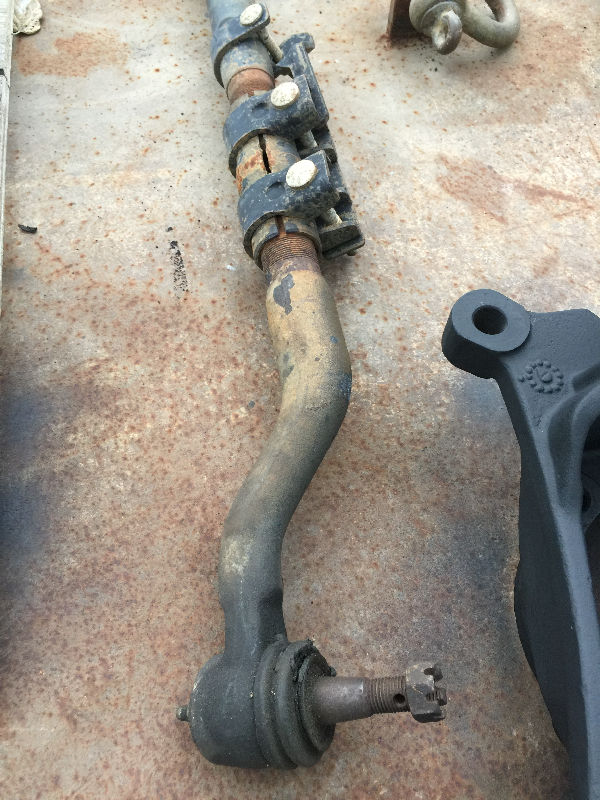 Tie Rod |
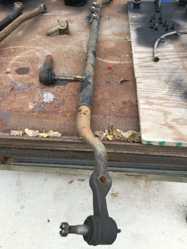 Tie Rod |
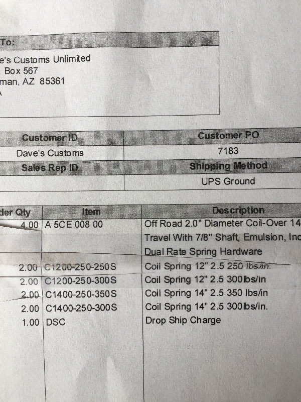
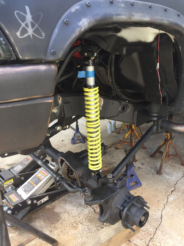
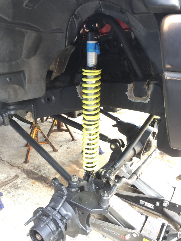
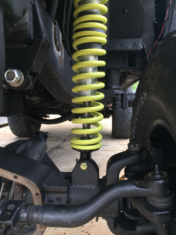
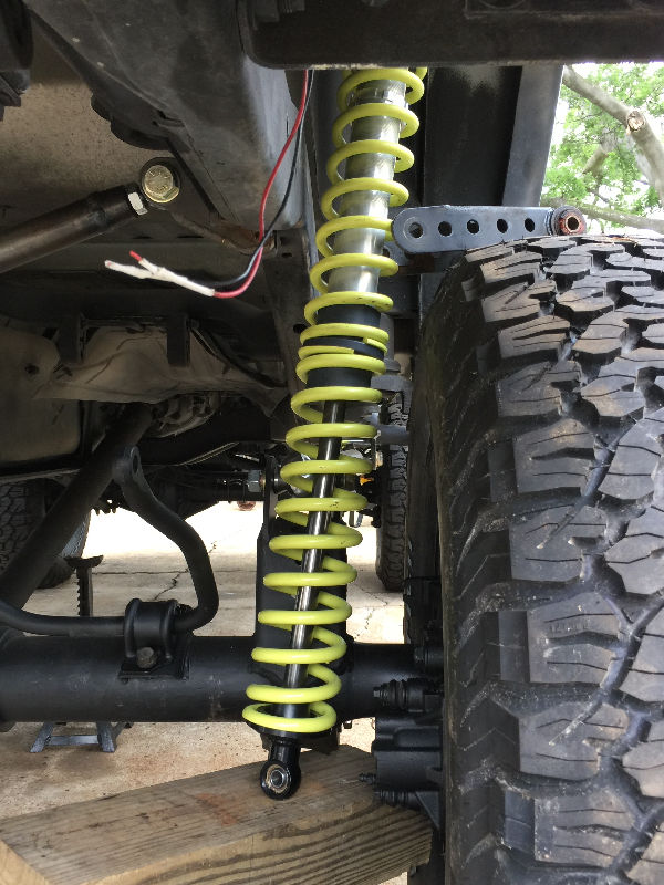
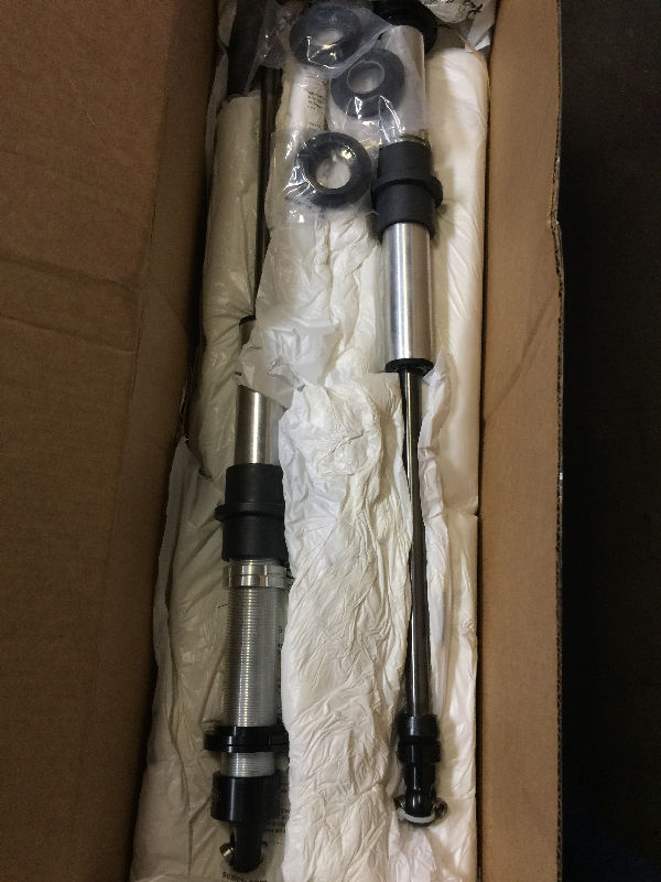 RadFlo 2.0 Coilover Shocks with 14" travel. They came charged with nitrogen |
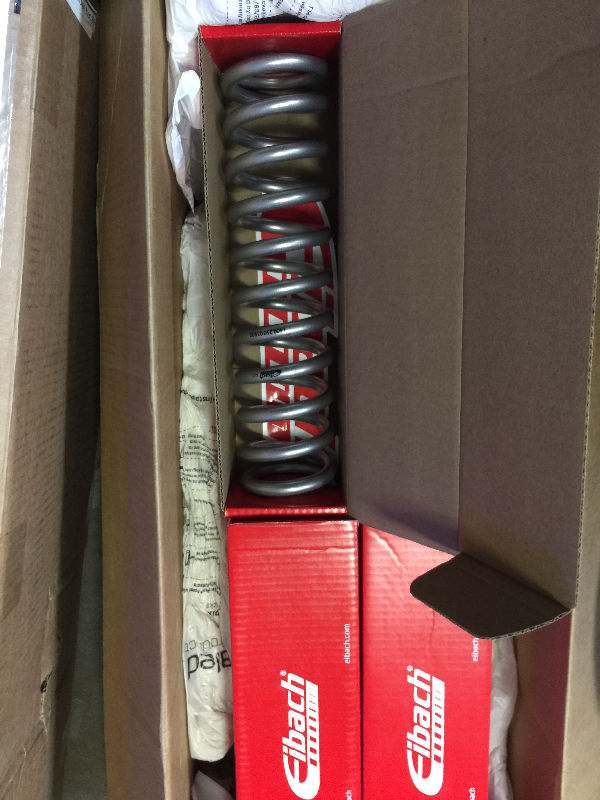 Coils that will go on the shocks |
 |
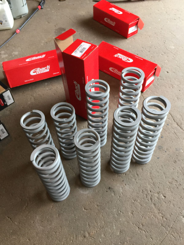 Coils were lightly sandblasted to prep them for paint |
 Painted |
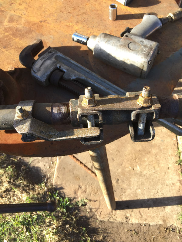 Drag Link being broken down for sandblasting and paint |
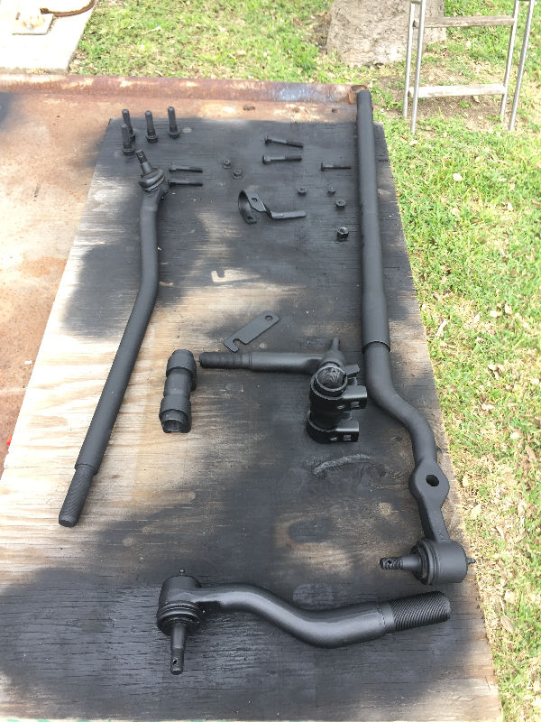 Both Tie Rod and Drag Link painted |
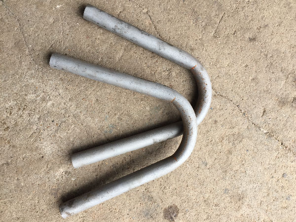
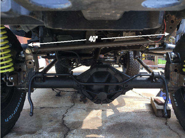
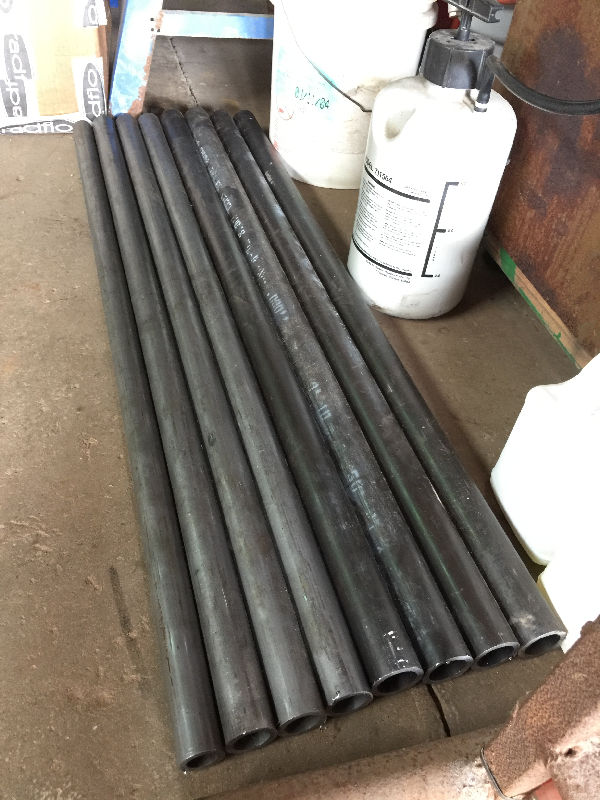 DOM Tubing cut to 40" lengths, minus the last piece I needed for the rear PanHard Bar. DOM Tubing cut to 40" lengths, minus the last piece I needed for the rear PanHard Bar. Here are the measurements of all my links cut to size with the Rod Ends welded in place. All measurements are eye to eye on the Rod Ends. Front lower links - 35 1/2" Front upper link - 26" Front Panhard Bar - 35 1/2" Rear lower links - 40" Rear upper links - 33" Rear Panhard Bar - 40" |
 Time to cut out the old |
 I started unbolted everything, but the lift kit along with that damn IFS had a bazzillion nuts and bolts. So I torched it all off. lol! |
 |
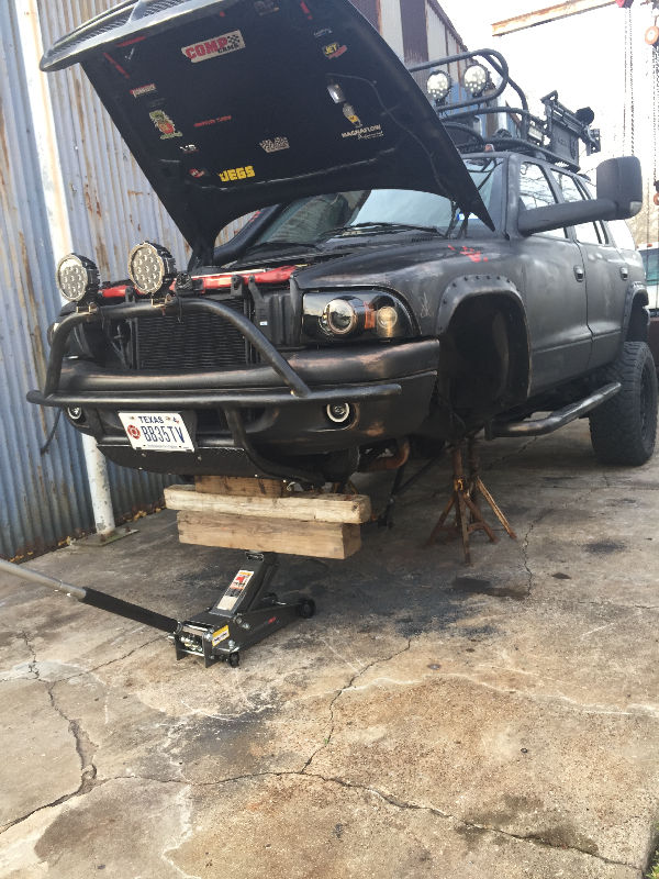 |
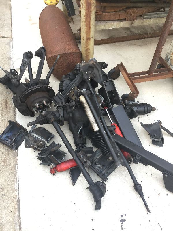 Front axle and lift kit |
 Grinding off the old shock mounts |
 |
 |
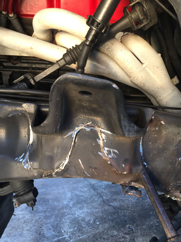
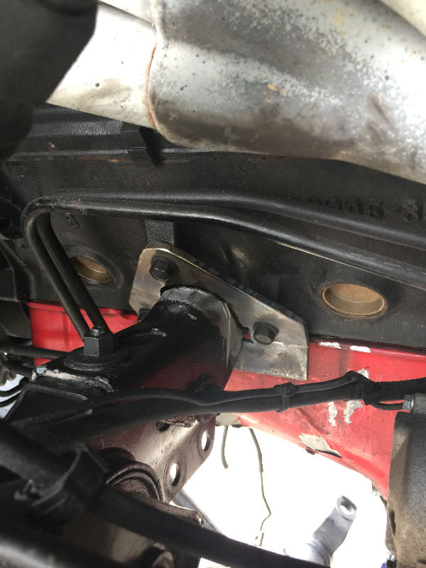
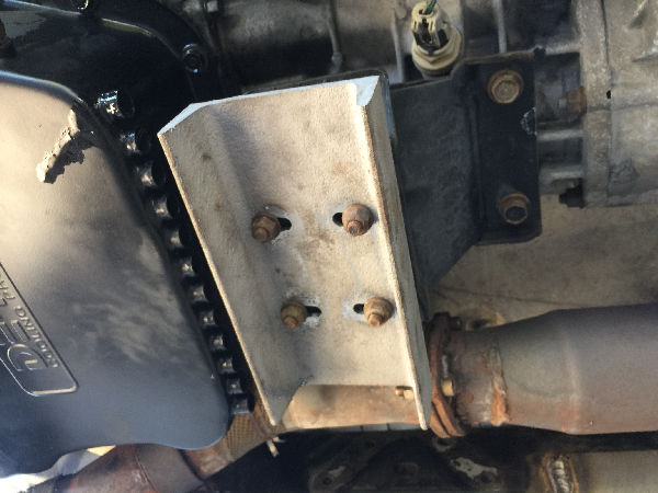
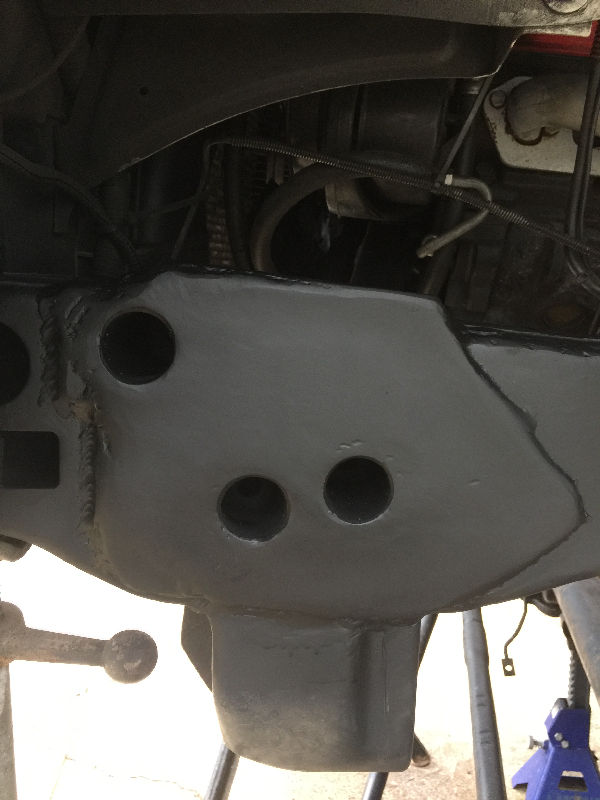
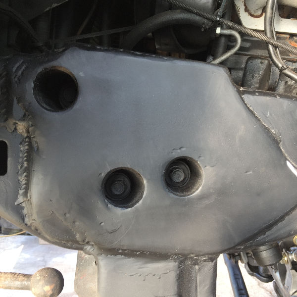
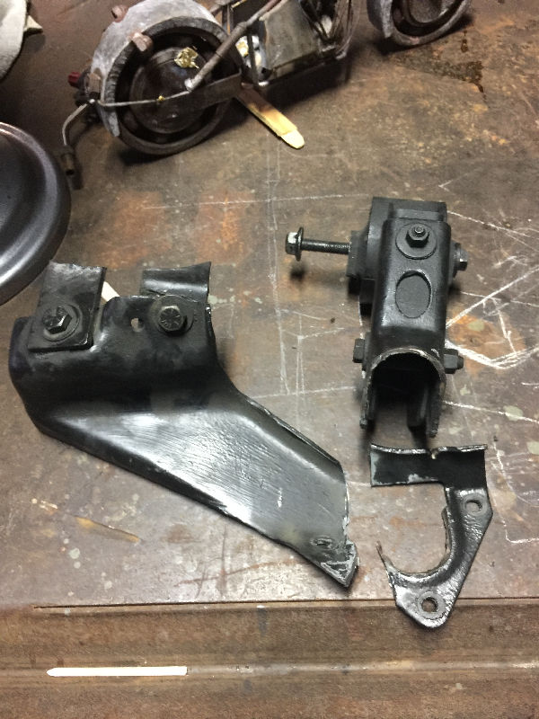 I had a broken motor mount, so i cut it off. I will not need the left part of the mount anymore. So I'll fabricate a new plate to weld to the motor mount. |
 This is where the factory weld was broken. |
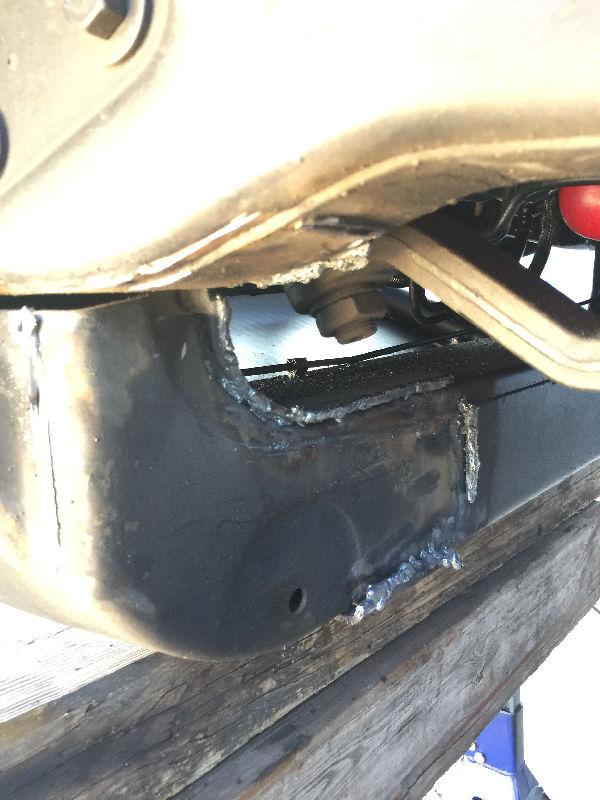
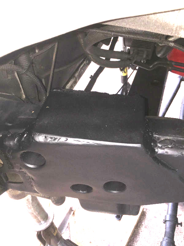
 Mocking up new plate for motor mount. Tack it in place, remove mount and weld out. |
 New plate welded to motor mount. |
 Definitely stronger than the factory welds. |
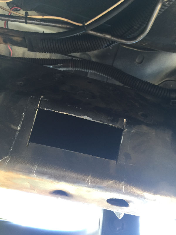
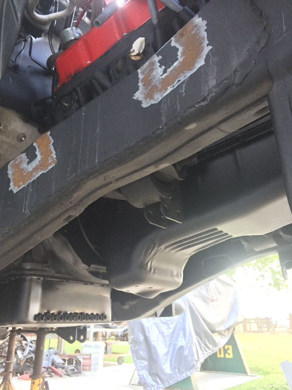
 You want to weld in a filler plate to cover up the dimples, plus to strengthen the frame. |
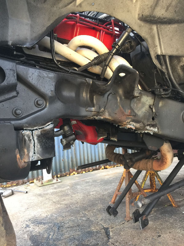
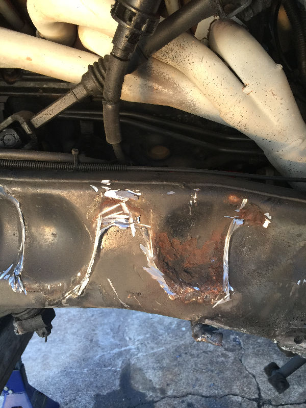
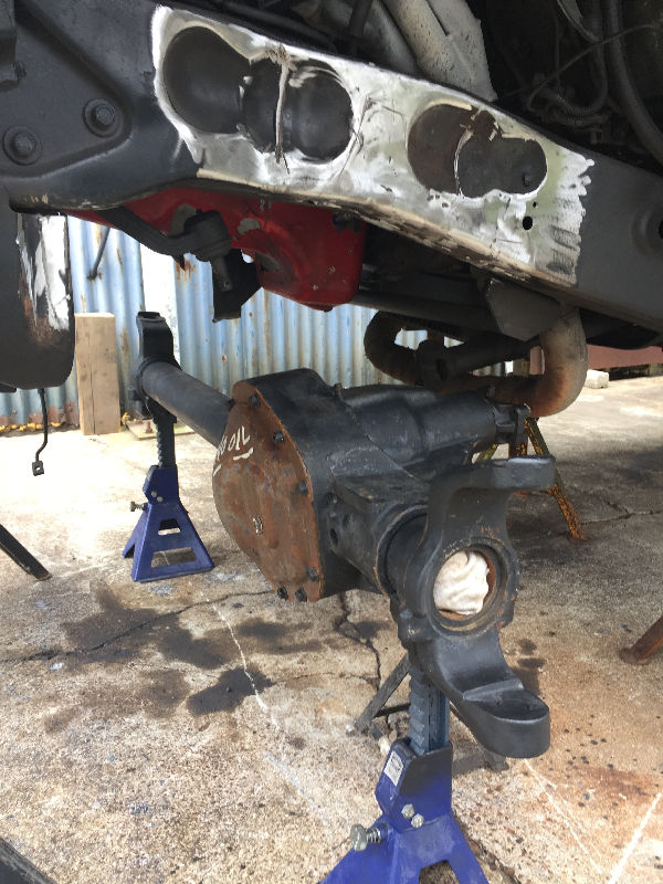
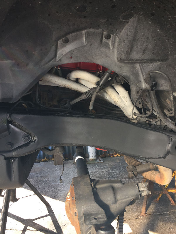
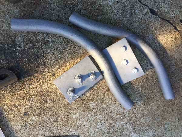
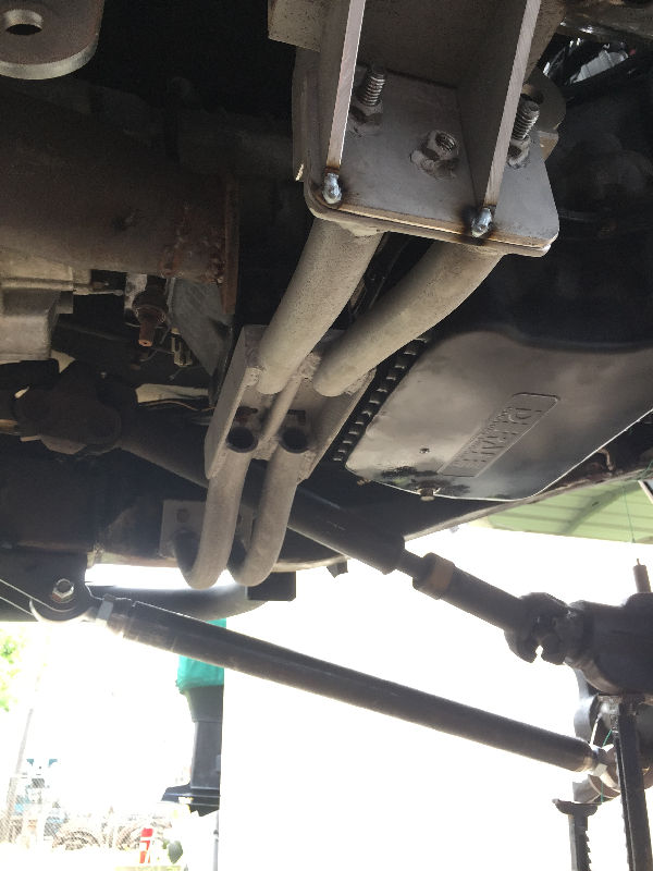
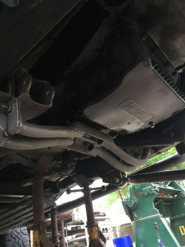
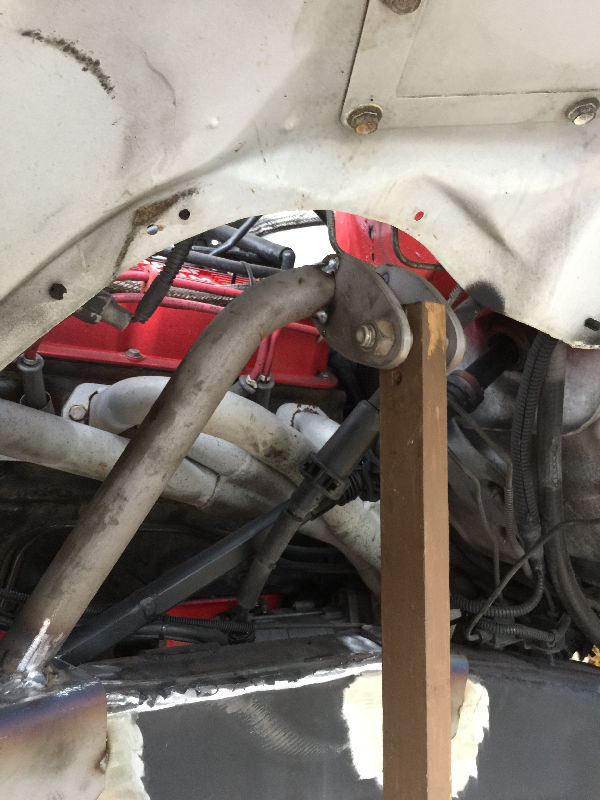
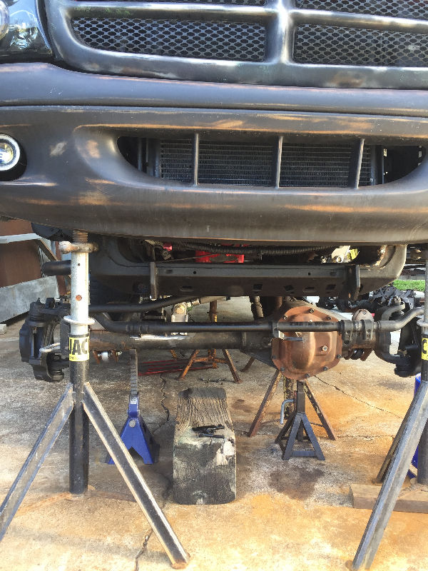
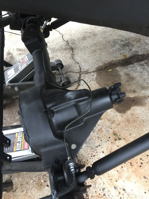
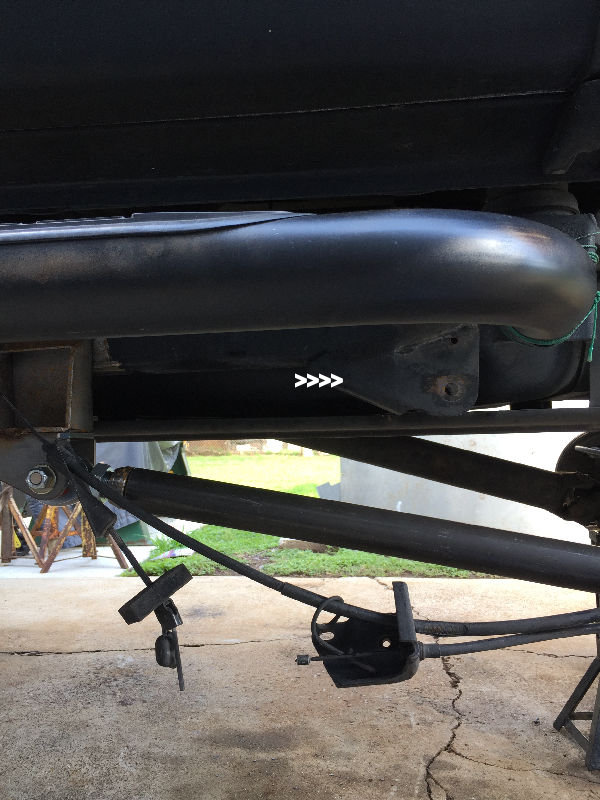
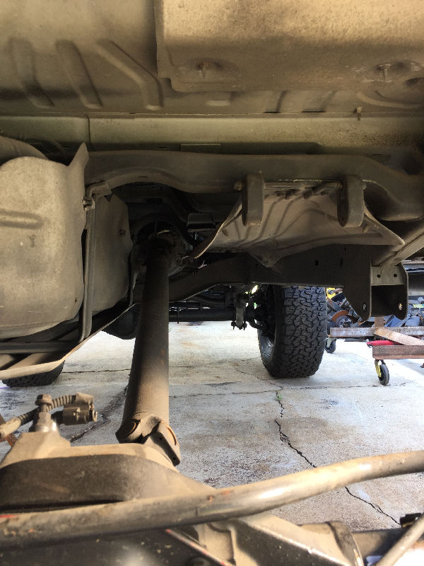
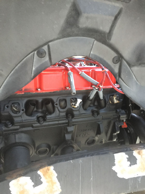
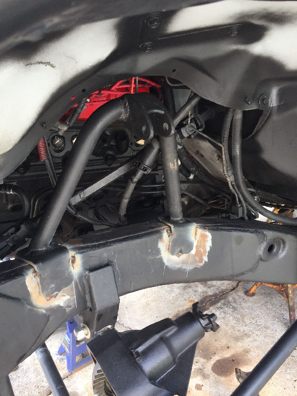
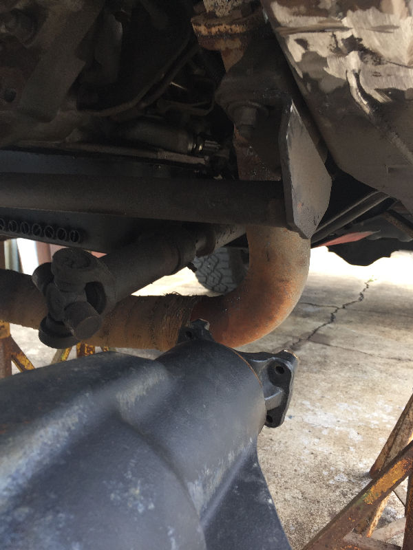 With new axle in place, I will have to remove exhaust crossover. The driveshaft hits it since the Dana 50 pumpkin sits further to the drivers side. |
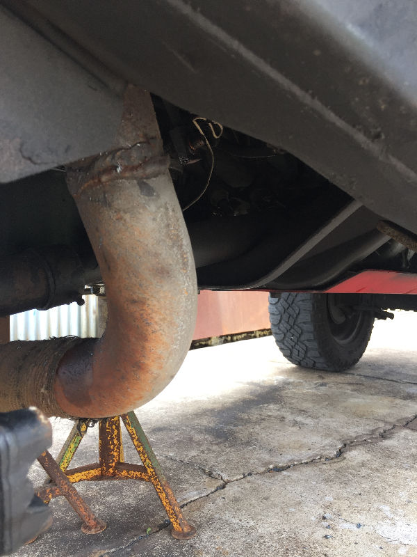 |
 You can see the exhuast drops down right in front of the pumpkin, before crossing over to passenger side. The entire exhaust from the muffler forward needs to be refabricated due to the links and mounts. |
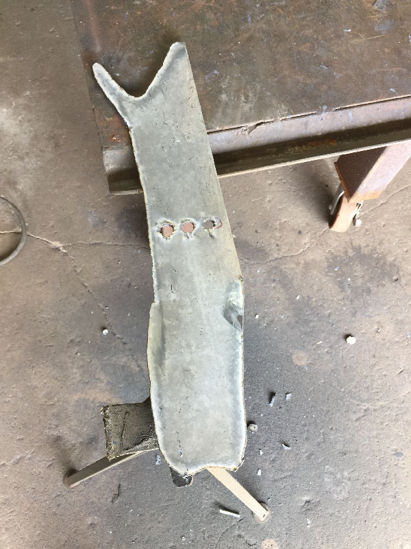 First I made a template from cardboard, then cut out a piece of plate to match it. This plate will be used to cover the dimples where the old shock mounts were. |
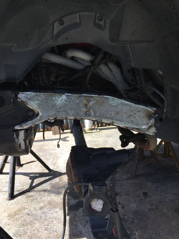 Welding it in place |
 Welded up for now, I will come back and fill in the weld as I snooth it out later. |
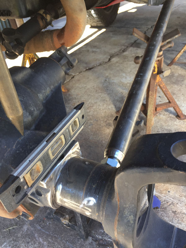
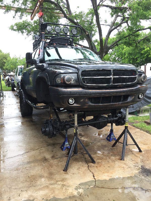
 To center the axle where you want it, place the tire up against the axle. You should have the axle off the ground at the measurements you wrote down earlier. Si the center of the axle matches the center of the rim, as if the rim is bolted on. The Durango should be at the ride hieght you wrote down earlier also. At this point, you can move the axle back, forward or keep it centered in the fender well. I kept it centered. |
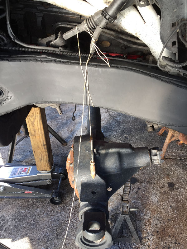 Once I set my axle, I used a plump bob to keep it centered. You should use a punch to mark where your string will always go. Punch on top of the frame, and don't weld over it or grind it away. The punch mark will always be your reference point to align the axle. Do this for all four wheels. This is for aligning the axles front to rear, not side to side. |
 |
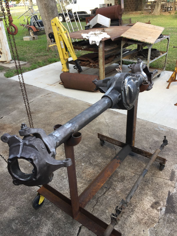
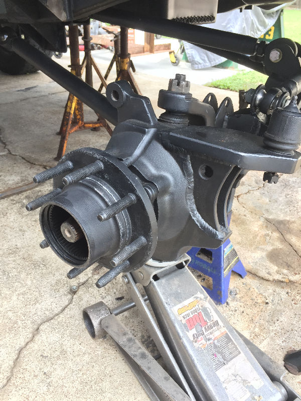
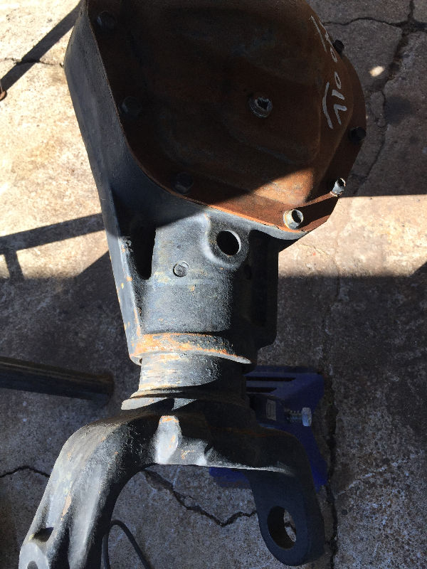 This Dana 50 had to be modified so I would have room to weld on my mounts. |
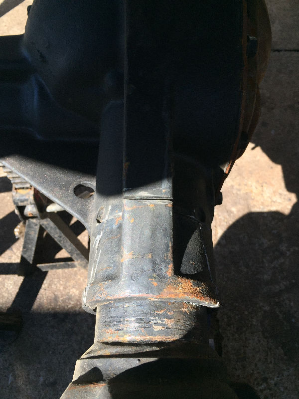 I had to cut and remove this section. A Dana 60 is wider, so this section would not be cut. |
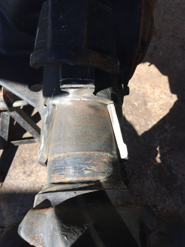 I cut out the upper portion at first, but ended up cutting it all the way around. |
 Placing the first link. Nothing is tack welded at this point. The insert is just placed inside the tube. |
 This is to get the angle and length of your link. Remember, it should not be no longer than 40" from eye to eye. During this entire process, keep checking that your axle has not moved at all. I recently saw another build where the guy had welded his axle in place with pieces of scrap metal. This held it true while fitting and tack welding all mounts. Then when ready, remove the scrap metal. |
 Once the length of the links are established, you can tack weld brackets in place. My Rod Ends are not welded yet though. My front bottom links are 35 1/2" eye to eye. |
 Leave enough threads showing on the Rod Ends for adjustments later on. |
 |
 The transmission crossmember was also keeping the front driveshaft from bolting up to the pumpkin. I never liked that thing anyway as it was always a pain to remove or workaround. So I fabricated up a new one out of DOM tubing. |
 This will be my new center piece of the mount. |
 I cut out this hole on the drivers side and I welded up one of the plates above to bolt the mount to. |
 Once the mount was welded together, I could bolt it in place. Once the mount was welded together, I could bolt it in place. |
 It's a lot cleaner and easier to work with now. |
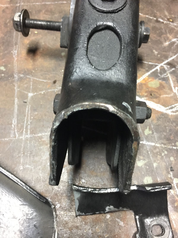
 With both mounting plates, I had drilled them out. That way I was able to weld the DOM tubing to both sides of it, increasing the strength. The bracket above it is where the upper links bolts to. The transmission, upper link and lower link brackets are all actually one mount that fits over the frame. |
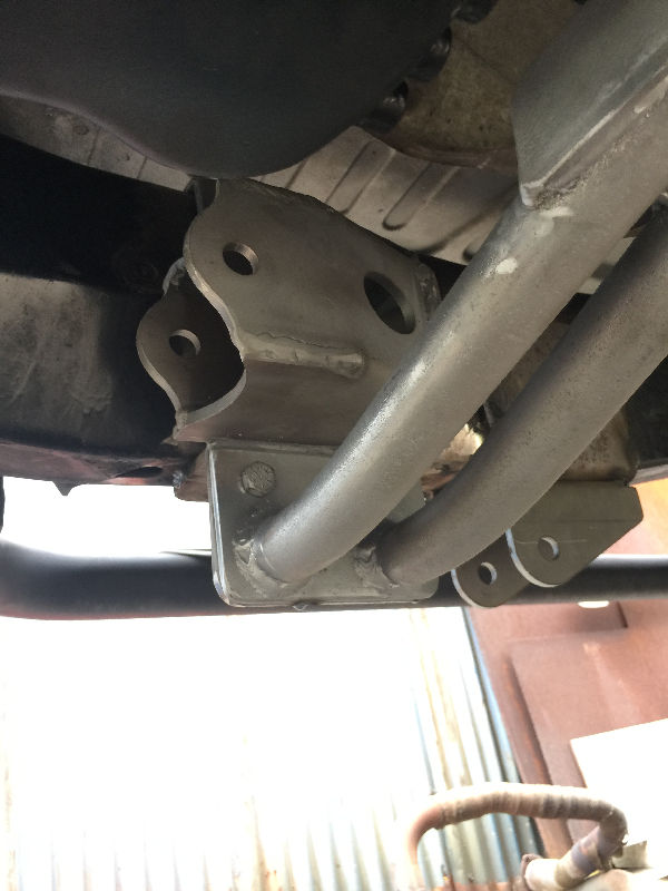 You can see the lower link bracket here. Once everything was tack welded in place, the whole piece was removed for welding out. Then placed back on frame and welded out. |
 We bent it enough on this side so that the driveshaft would not hit during articulation. |
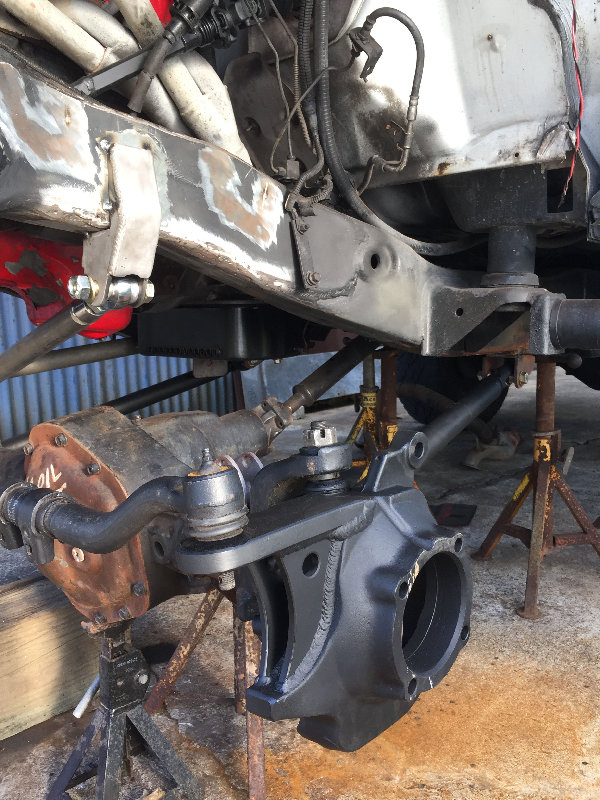
 The pitman arm does not line up with the drag link. The pic shows the pitman arms position with the steering at dead center. The drag link runs straight across with the tie rod, but ends up behind the pitman arm where it should attach. So I had to move the steering box forward 4" on the frame. |
 The pics are after we completed the fabrication on this part. I'll explain the process though. Using cardboard again, I made templates to cut out my plate. Three pieces were used. The outside frame here, the top, then inside. |
 |
 I used the stock bolts to bolt down the steering box. So once all three plates were tacked together and in place on the frame, we positioned the steering box where we wanted it. Then marked the holes, pulled the bracket out, drilled it and welded it. We also drilled the plate on the outside so we could insert three pieces of pipe later. After the bracket was tacked back in place, we drilled out the frame. Then bolted the steering box in place. We then inserted the three pieces of pipe, cut them to sit just below flush of the plate and welded them out. Later when the welds were filled in, then hit with a Tiger Paw to smooth it all out, this gave it a clean look. |
 |
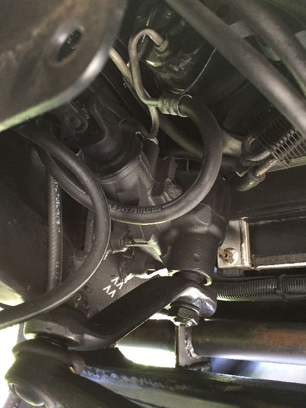 The arrows are pointing to spacers we welded on. This was done to keep the steering box flat with the plate. It actually sat in a big dimple on the frame in its stock position. All the hydraulic hoses will fit, though you might have to bend the metal lines here and there. |
 |
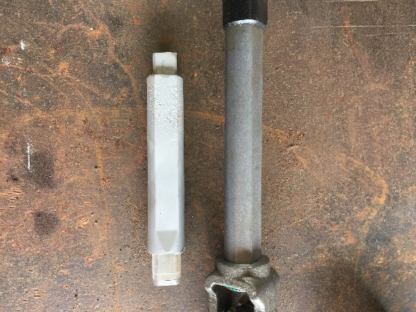
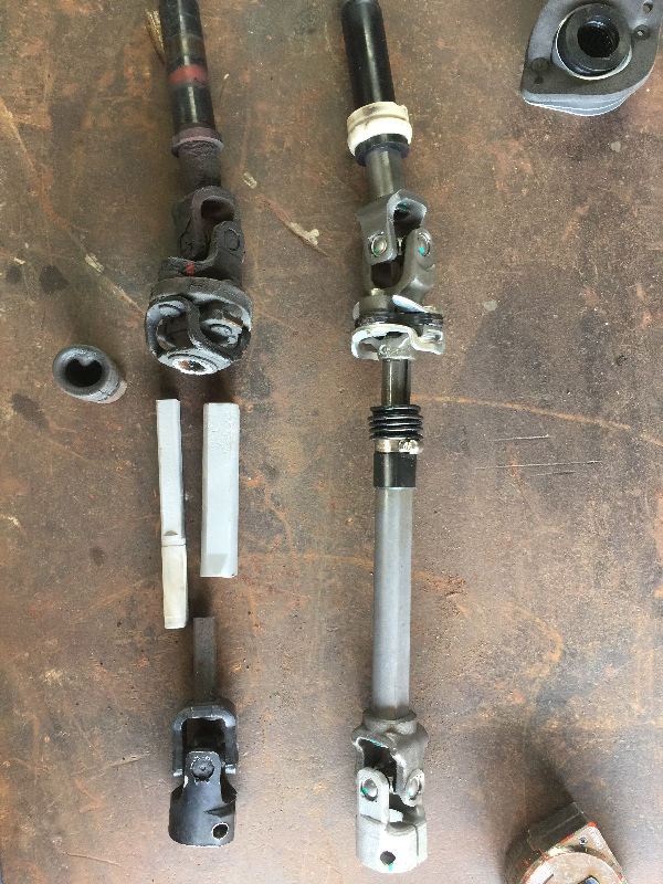 We had to fabricate a longer intermediate steering shaft now. So with mine being so old and worn, I ordered a new one. Then cut four inches from the old one, (the two sandblasted pieces shown). |
 Place the solid piece back inside the hollow body. |
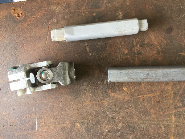 We then cut the new shaft at the end that bolts to the steering box. |
 Slipped the solid piece into the new shaft on both ends. The soid piece should fit into the knuckle about 1/2" or so. |
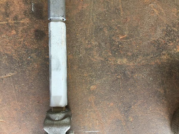
 We did bevel the ends before welding. This pic shows the gap needed to get good penatration into the solid piece. |
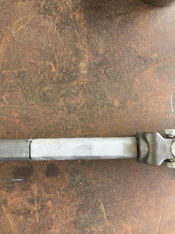
 After welding out, we cleaned up the weld on the shaft with a Tiger Paw and painted. |
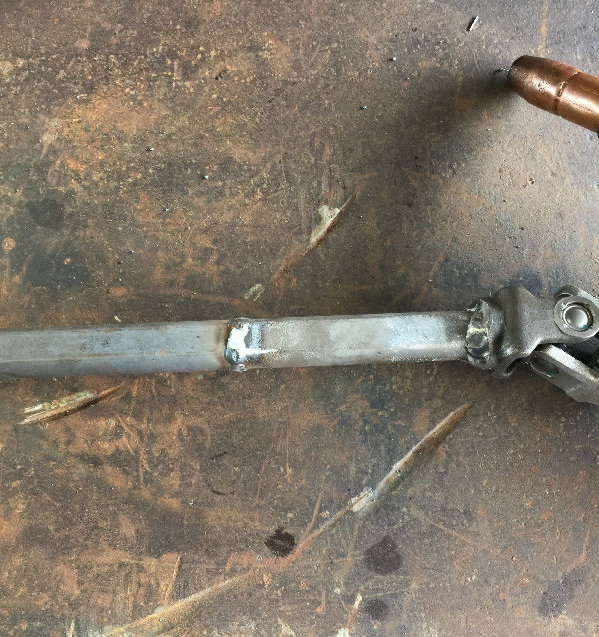
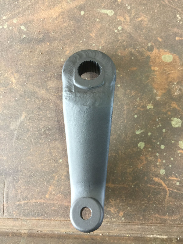
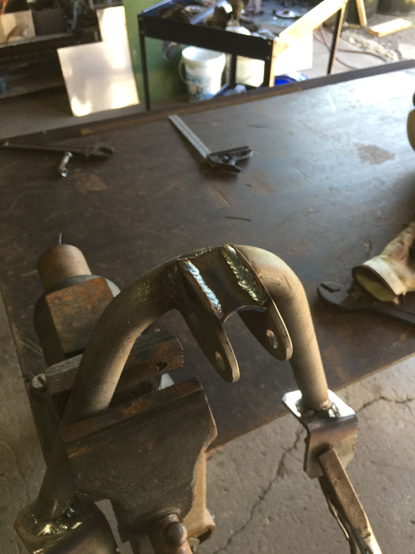
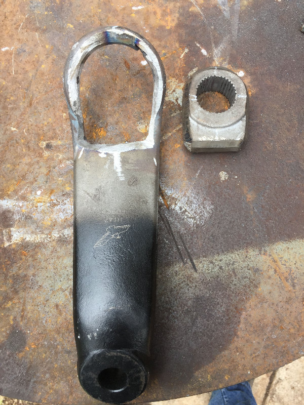 I ordered a Ford pitman arm and drilled out the end that goes onto the steering box. I cut off the end of my old one, ground it down to fit into the Ford pitman arm. Then beveled everything, pre-heated and TIG welded in. Two things, be mindful of the soapstone marks above. They mark notches in the teeth and the side that slips up onto the steering box. This part is beveled and only fits one way to bolt down. Both holes are beveled, so make sure you mock it up on the Durango first before welding out. After TIG welding, it was wrapped up tightly in a welding blanket to cool off very slowly. |
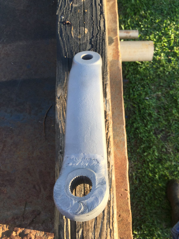 Now I have a Ford/Dodge pitman arm. You can actually find companies online that fabricate these up. |
 |
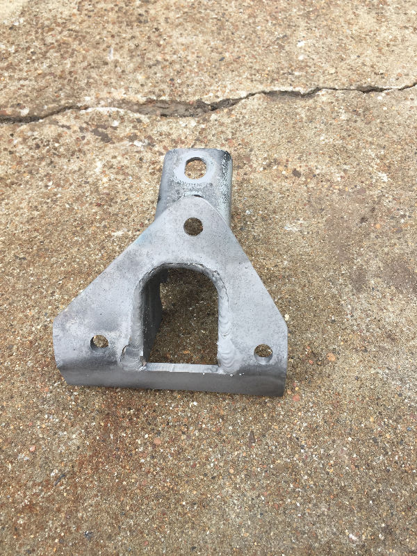
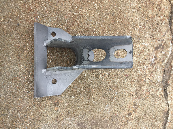
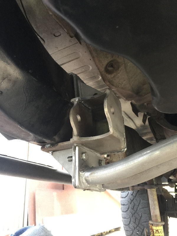
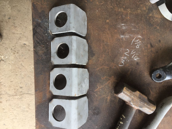
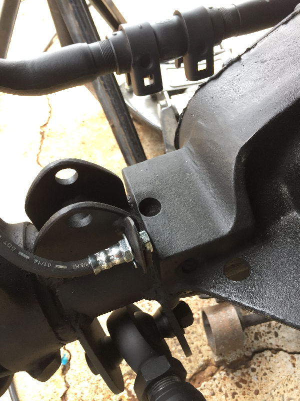
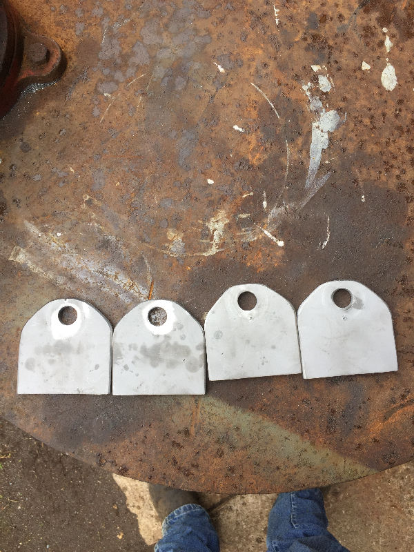 Brackets fabricated for lower front shock mounts. |
 Once bolted on, we tacked in a piece to keep them spaced apart. The next pic shows this piece. |
 |
 The lower shock bracket sitting place. |
 Bent DOM tubing for the front shock hoops. |
 These pieces are the feet of the shock hoops. We drilled them big enough for the tubing to slip through them. We then placed them on the frame, place the hoops in them, set the angle on the hoops and tacked them to the feet. Then removed them, cut down any excess underneath them and welded out the top on bottom. |
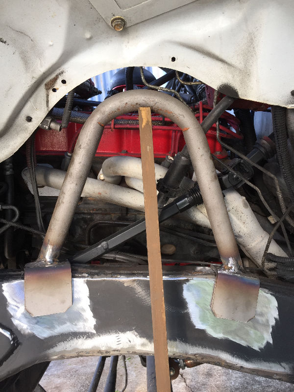 Sitting in place on the frame. |
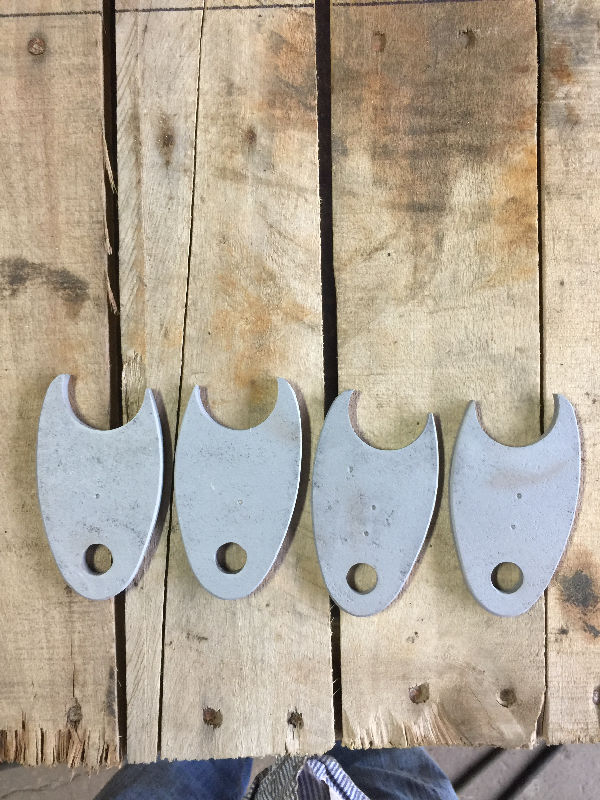 These are the top brackets for the shocks. |
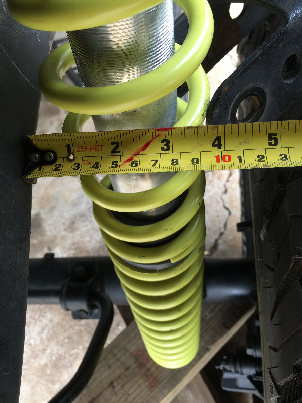
 We tack welded the hoops to the frame. Then using my calculations for *Proper Shock Length, which is 26" eye to eye, I drilled out a stick. With the bottom brackets tacked in place, we bolted the stick to them and also the top brackets. Then place the top brackets on to the tubing and tack in place. Then cut the tacks to remove for welding out. Be sure to use the stick later when you go to weld the hoops and bottom brackets permantly in place. |
 The top brackets welded in place with a brace. |
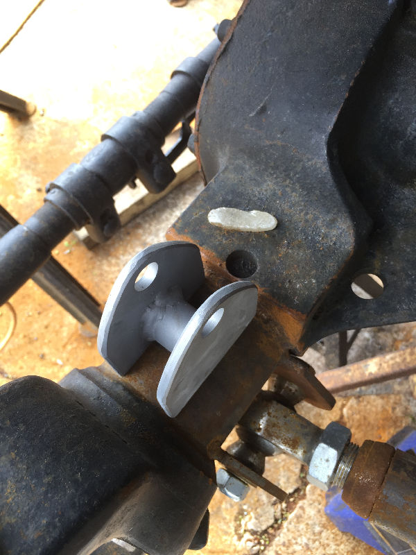
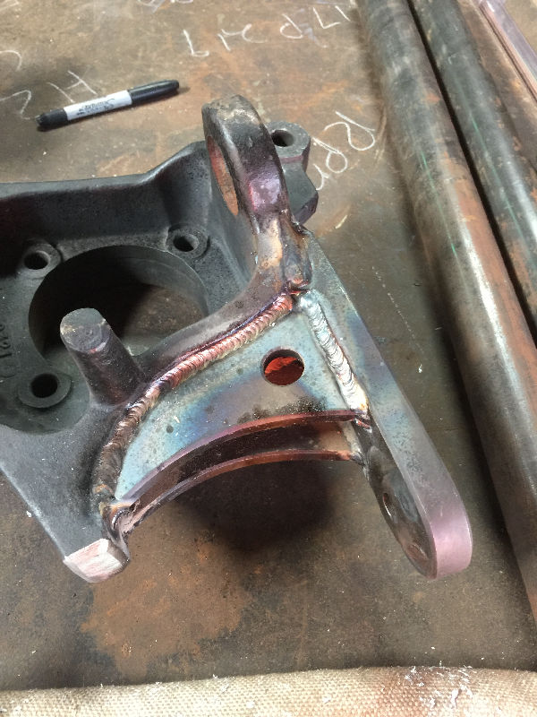
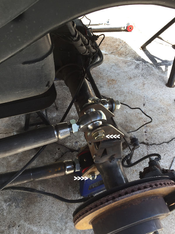
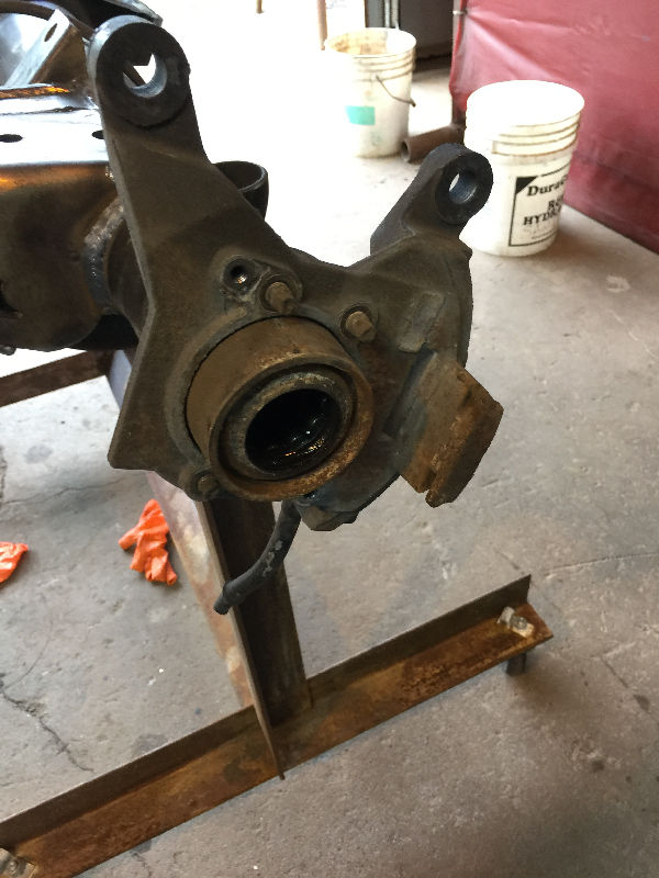
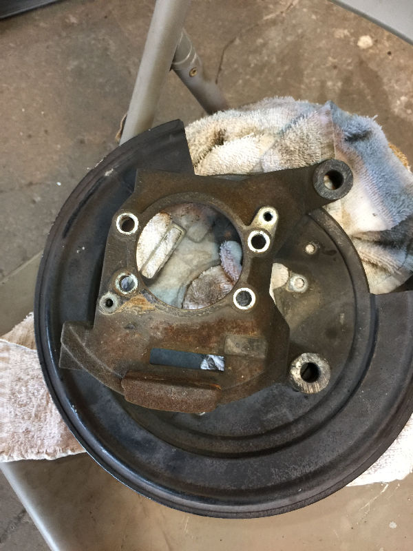
 Prepping the steering knuckles for a high steer setup. |
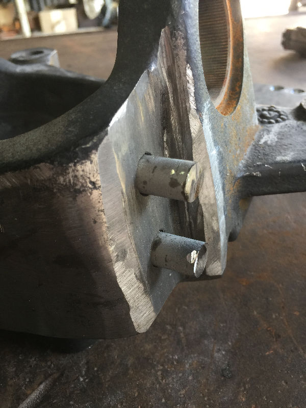 Drilled two holes, then welded some round stock in them. |
 This is where we welded the round stock in place. |
 The Tie Rod will bolt to these when done. They fit over the round stock. |
 These inserts were cut off the knuckles. Make sure you pay attention to the tapered holes, so the Tie Rod will fit properly in each one. |
 Tack welded in place. |
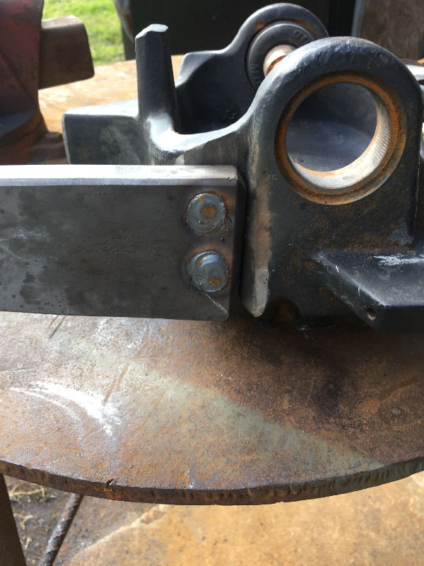 Then welded out. |
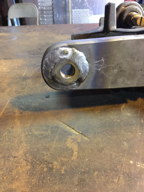 The inserts were TIG welded in top and bottom. |
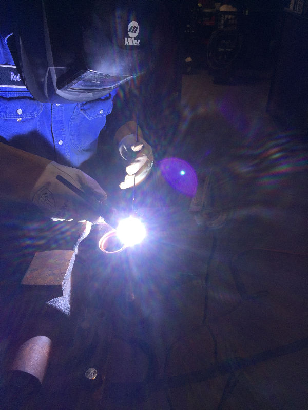 |
 Then the slow process of preheating and TIG welding the arms in place. |
 Gussets were added for strength. As each one was finished, it was wrapped up in the welding blanket to slowly cool off. |
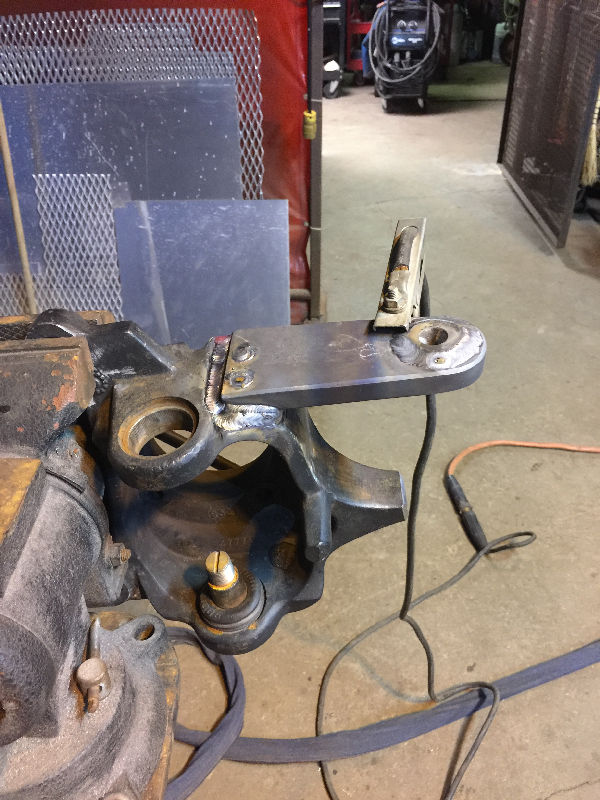
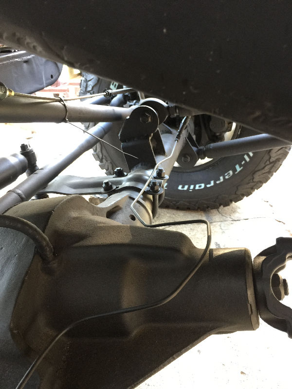
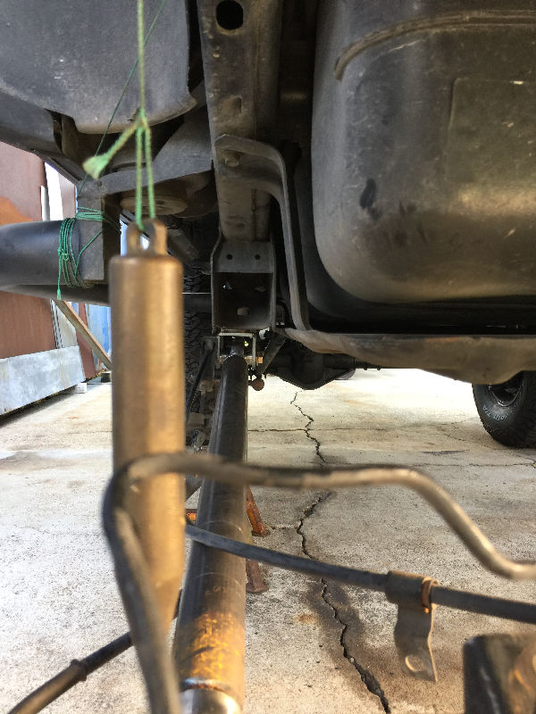
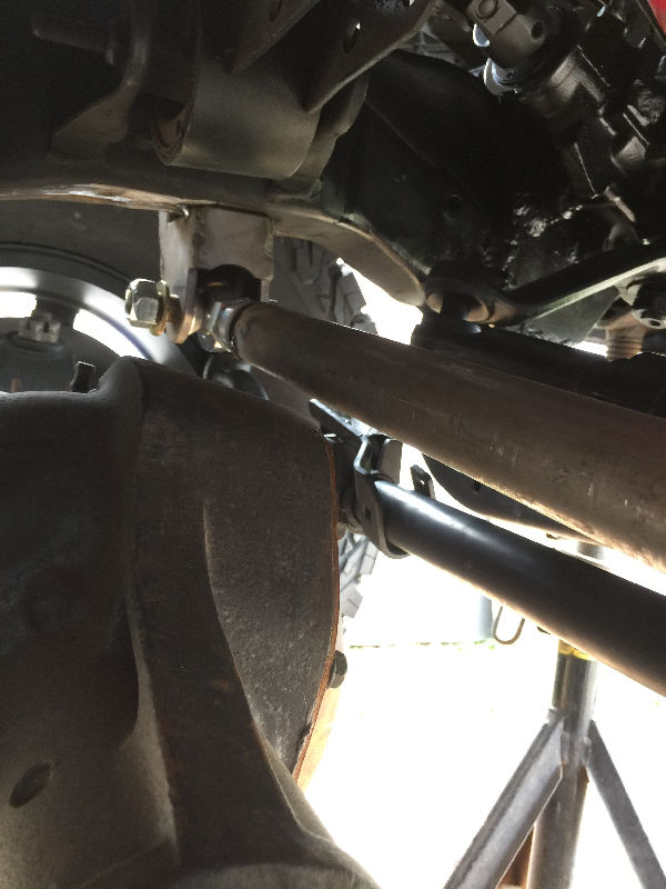
 With the high steer now in place, I can set my Pan Hard Bar. The Pan Hard Bar should run parallel to the Drag Link and be as close as to the same angle and length as possible. Also the more level the Drag Link and Pan Hard Bar are at ride height, the more stable the vehicle will feel. You can see where my Pan Hard runs parallel with my Drag Link, but it is way to short after talking to Dave at Daves Customs Unlimited. I needed it to run as far as possible to the end of the axle on the passenger side. |
 |
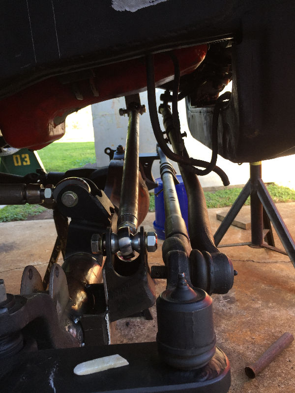 I fabricated a new mount and cut a longer Pan Hard Bar. It ended up being 35 1/2" eye to eye. |
 It runs parallel with the Drag Link and I even put a bend in it to match the Drag Link. |
|
|
|
|
|
|
|
|
|
|
|
|
|
|
|
|
|
|
|
|
|
|
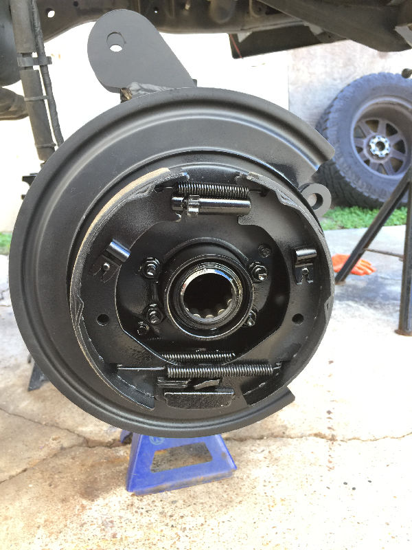
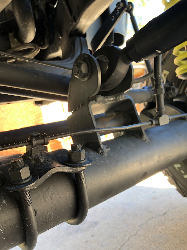
 We welded the brake hose brackets that came with the hoses to the lower shock mounts. Then usef the clips to secure the hose on both sides. |
 The white arrows point to the bracket on the passenger side. |
 This pic shows a better view of the bracket and retaining clip holding the hose. |
 Passenger side bracket |
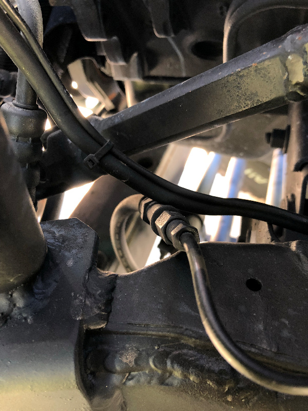
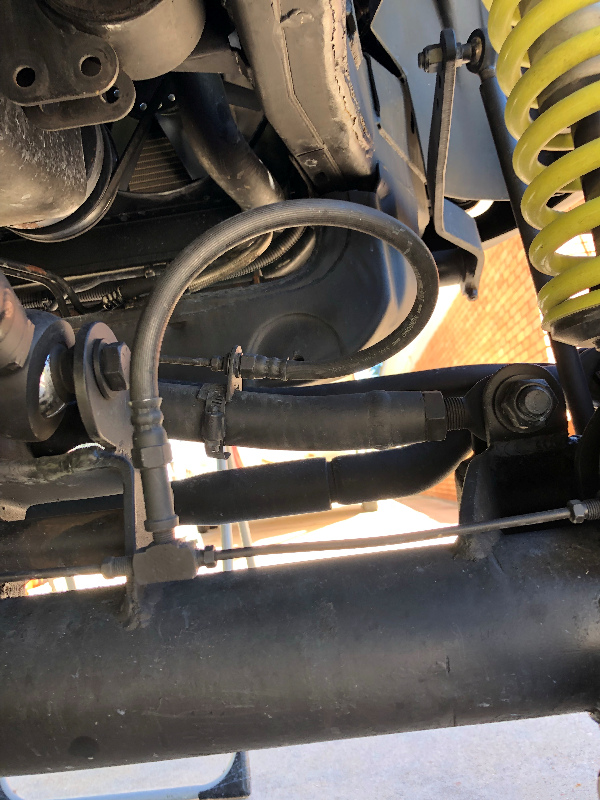
 The white arrows point to where the front brake line come off the Distribution Block. |
 This white arrows point in the direction the front brake line runs. This line used to run to the junction block on the frame that I had cut off. It connected to the junction block, then two lines came off the junction block and ran to each front wheel. Now the line turns and runs up the frame towards the front of the Durango. |
 You can see how the line runs forward before turning down towards the inside of the frame. |
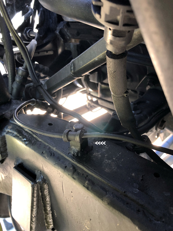 The white arrows point to a block we welded to the frame, after drilling and tapping it to hold the brake line secure. Then it continued, turned inward to connect to a flex hose. |
 |
 |
 The flex hose then connects to a hard line, runs down the Pan Hard Bar, then connects to another flex hose that crosses over to the axle. The flex hoses are for when the suspension articulates. |
 First flex hose connection. |
 The first flex hose connection after it has been secured to the Pan Hard Bar. With the stainless hose clamp, all we have to do is loosen it up to adjust the Pan Hard Bar. |
 The second flex hose as it crosses over to the junction block at the axle. This is the junction block I cut off the frame. So from here, the brake lines run to each of the front calipers. |
 The second flex hose secured to the Pan Hard Bar. |
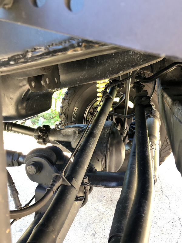 A full shot of the brake setup running down the Pan Hard Bar. |
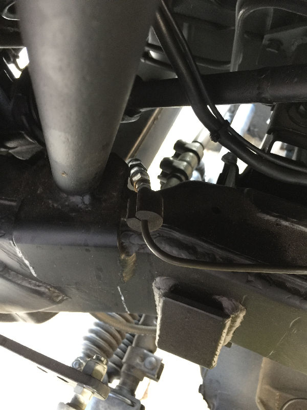
 We bent the brake line as it comes off the junction block to conform around the pumpkin. |
 Then connected it to the brake hose going to the caliper. |
 Another block securing the brake line in place. |
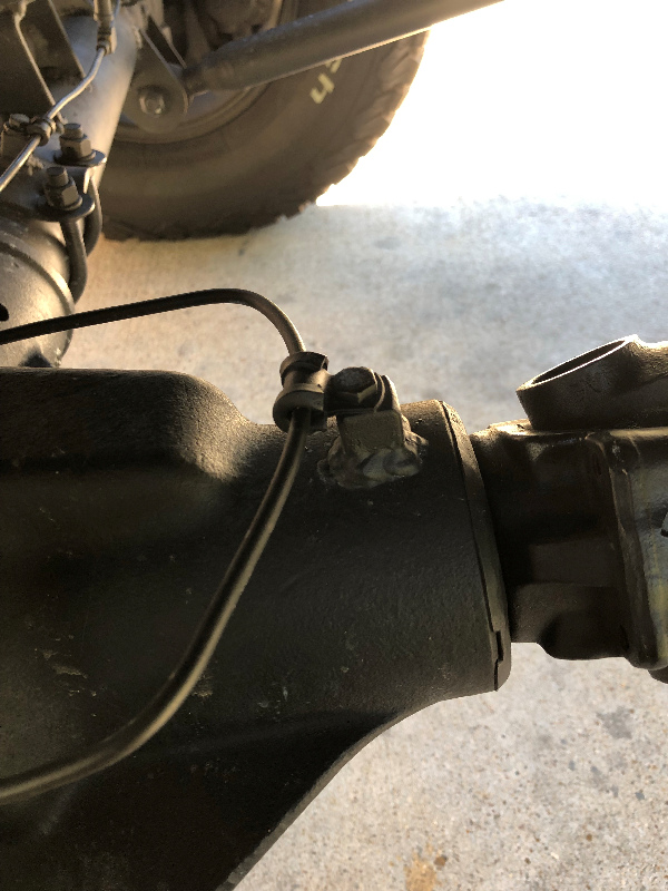 A block securing the brake line at the pumpkin. |
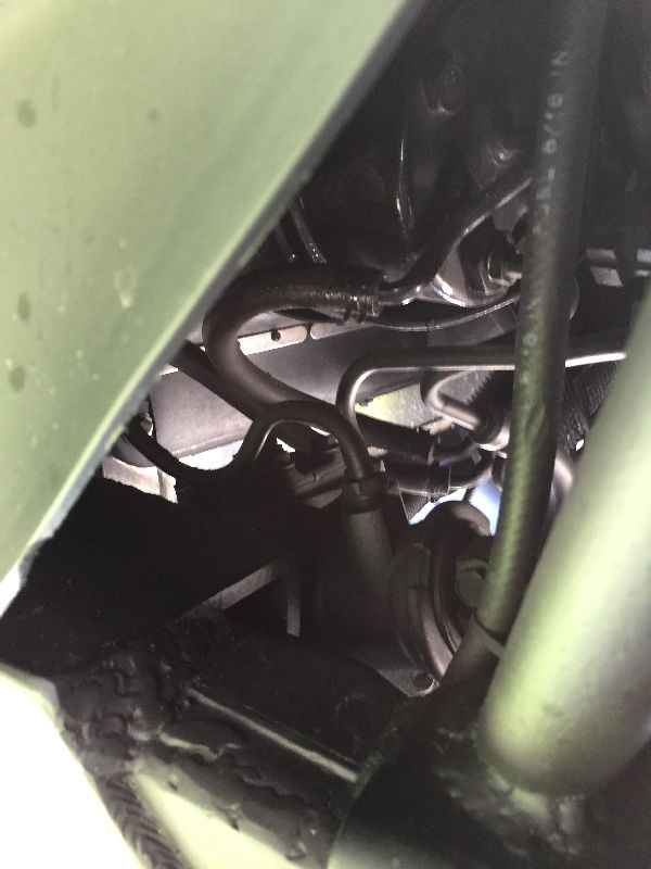
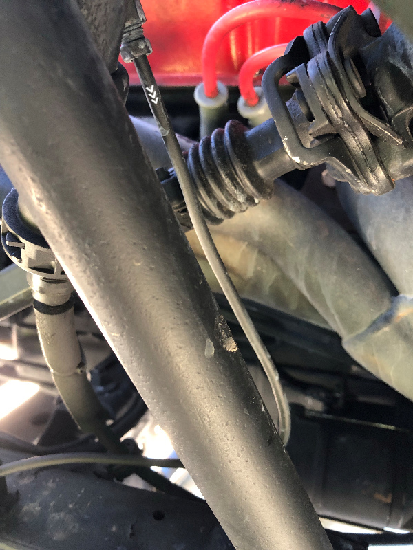
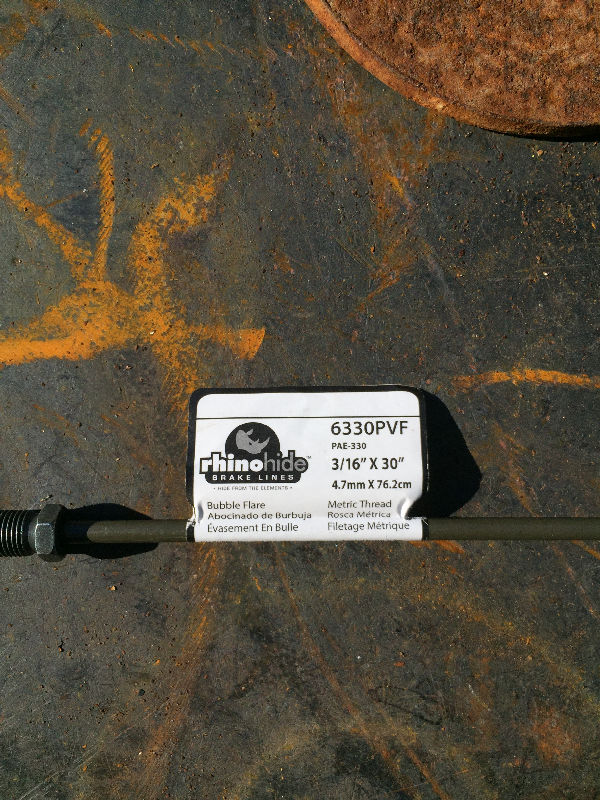 One of the many brake lines I went through for this setup. The Dodge side are Bubble Flare fittings and the Ford side are standard brake line flare fittings. |
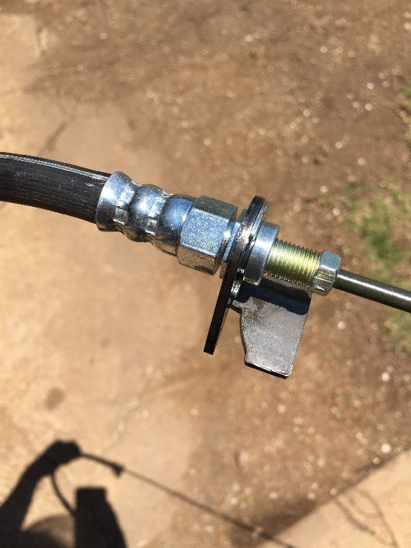 I ordered these retaining brackets online. |
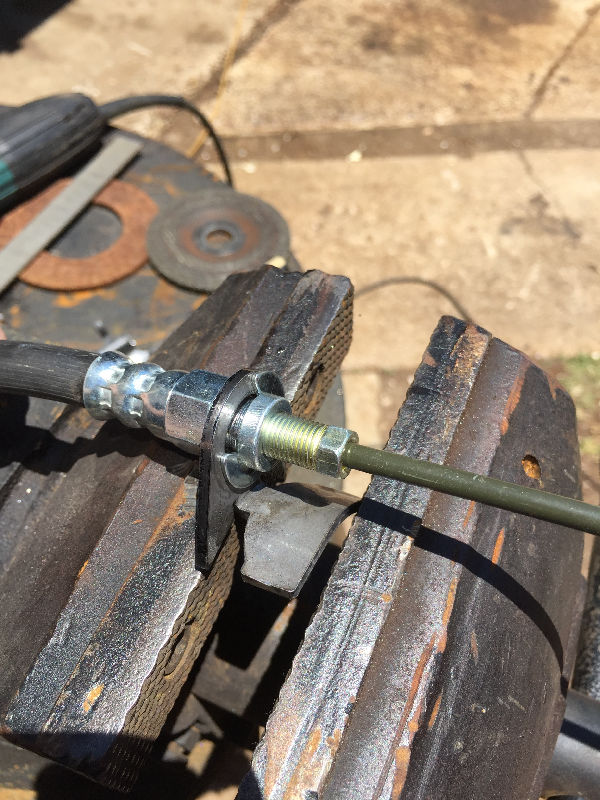 They come flat, so we had to put a small bend in them to conform to the Pan Hard Bar. |
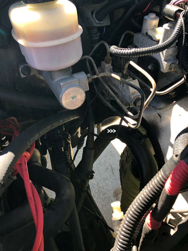
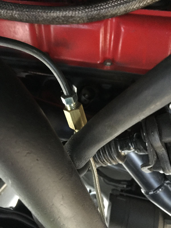 This brass fitting is made for Bubble Flare to Standard Flare fitings or vice versa. This where the Dodge brake line comes down from the Distribution Block up under the Master Cylinder. I got all my brake line parts at O'Rielly's Auto Parts. |
 Rainy days suck |
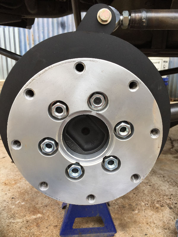
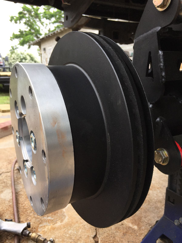
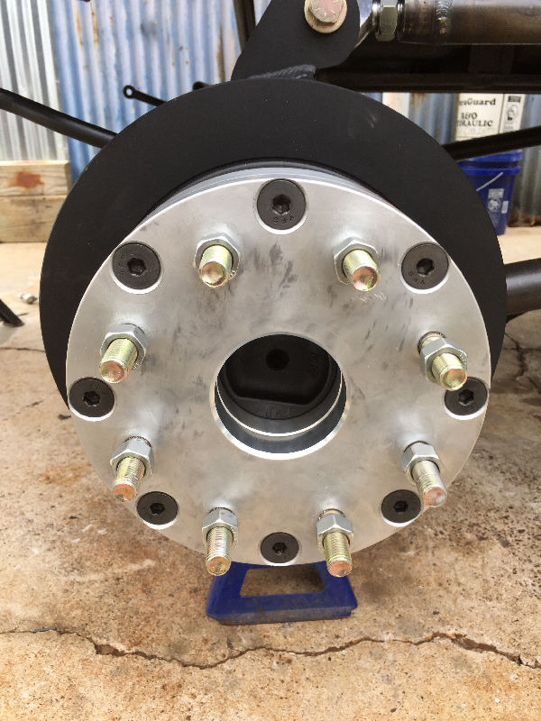
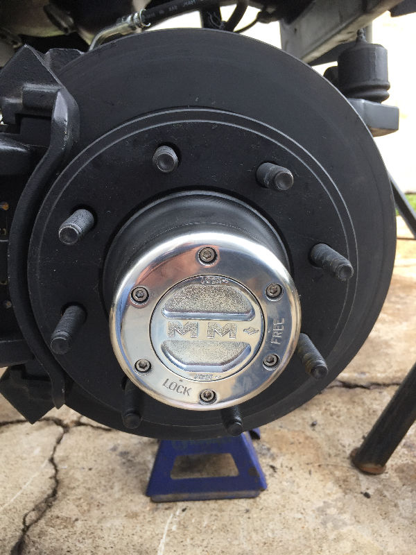
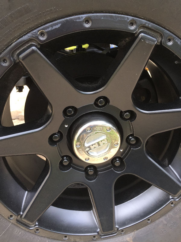
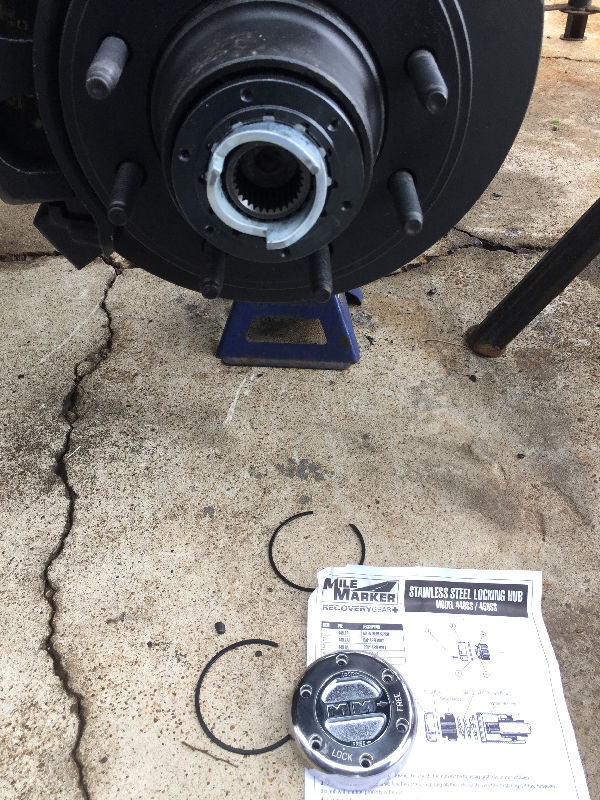 Installed stainless Mile Marker Lockout Hubs Part #449S - $162.36 Installed stainless Mile Marker Lockout Hubs Part #449S - $162.36 |
 |
 |
 |
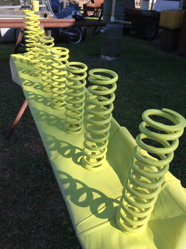
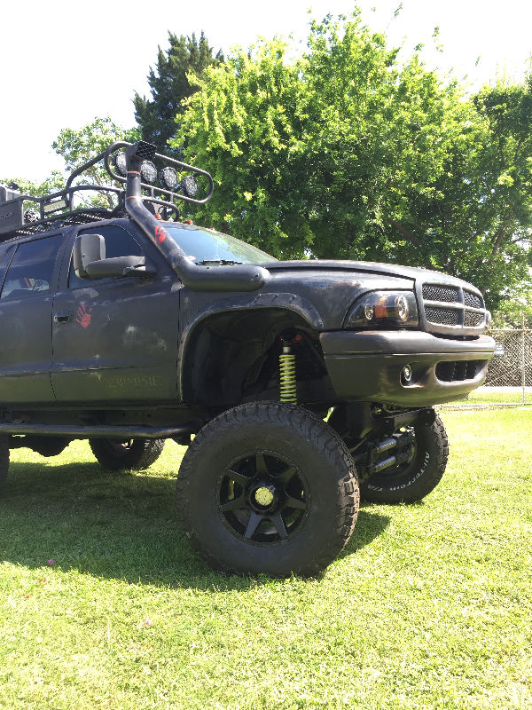
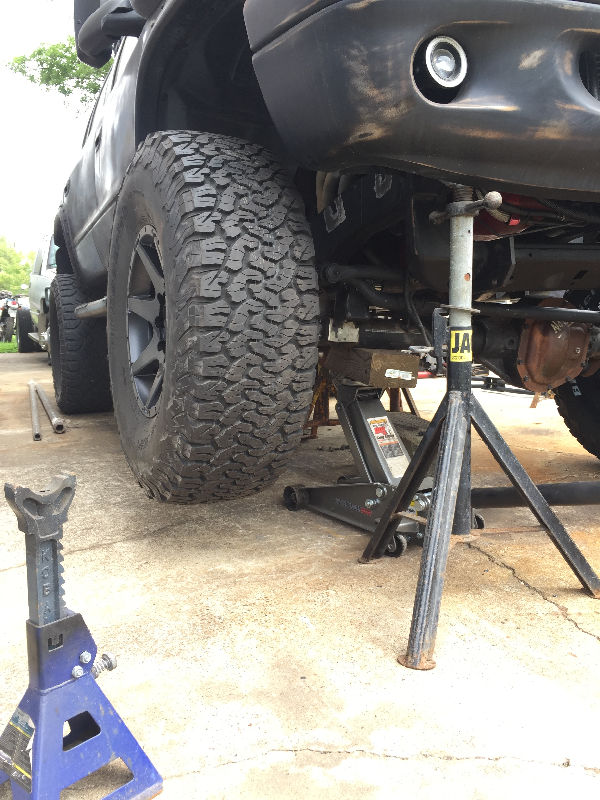
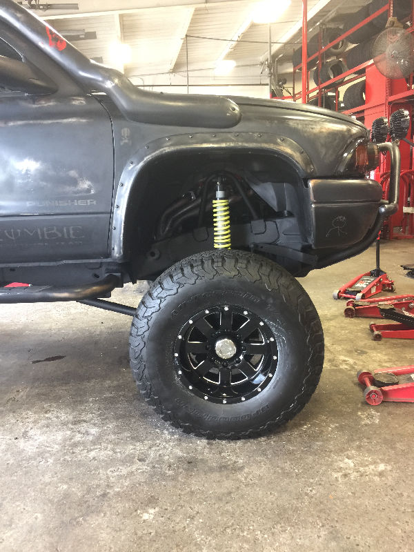
 Coilover set to ride height |
 |
 |
 |
 |
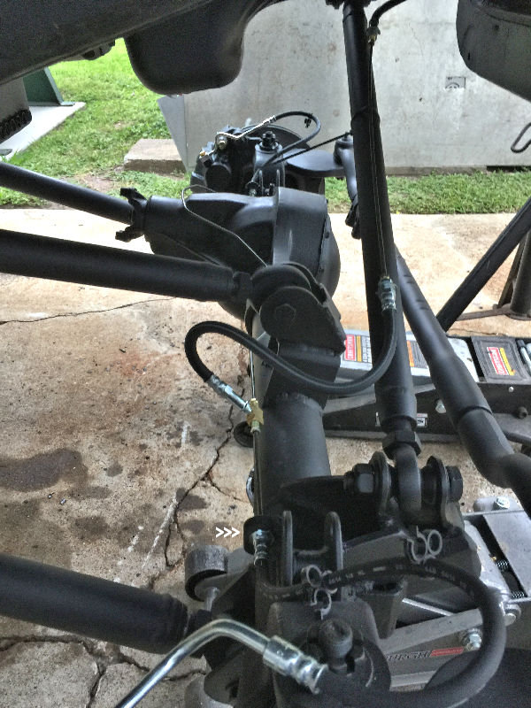
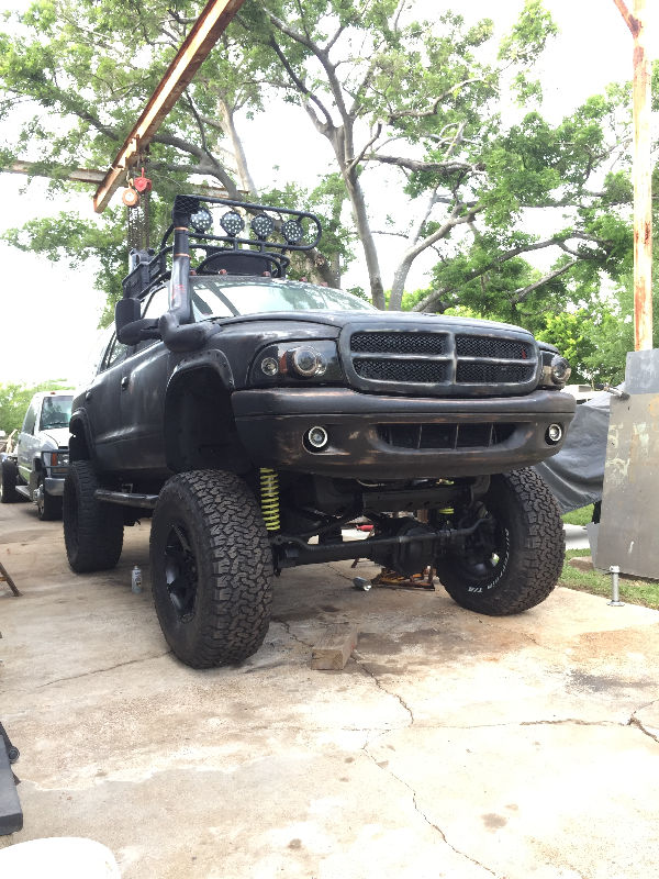
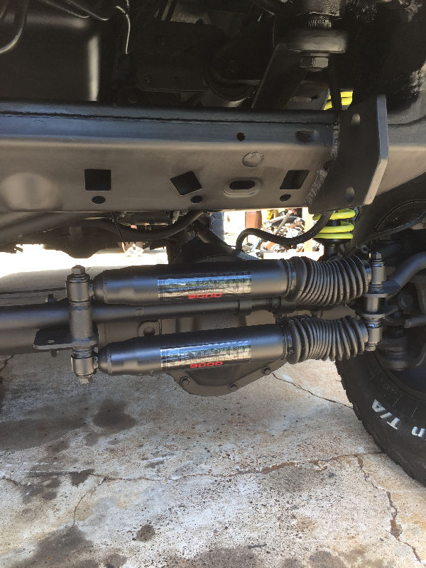 Skyjacker 9000 steering stabilizers. We had to modify the brackets to get the fit I wanted. |
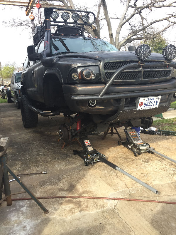
 Pulled it out to turn it around and start on the rear suspension. |
 |
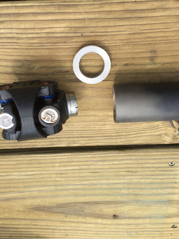
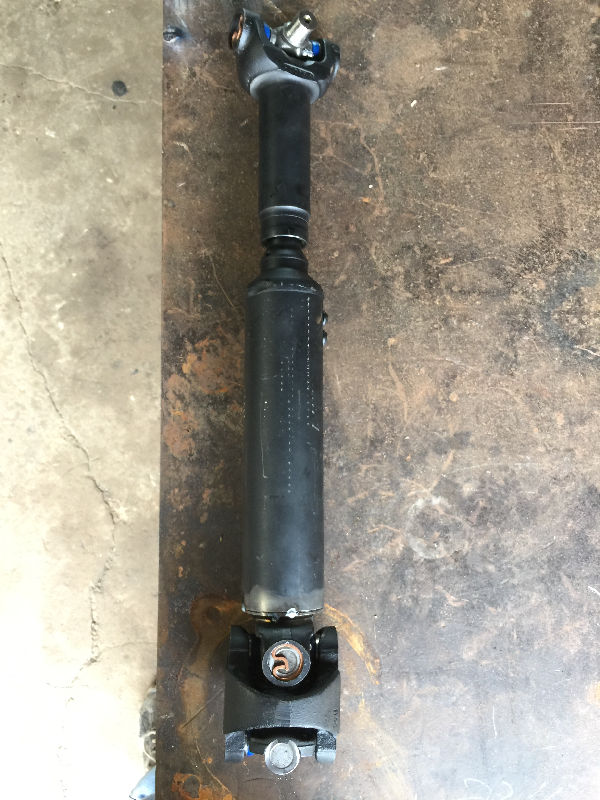
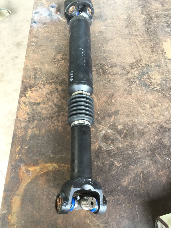
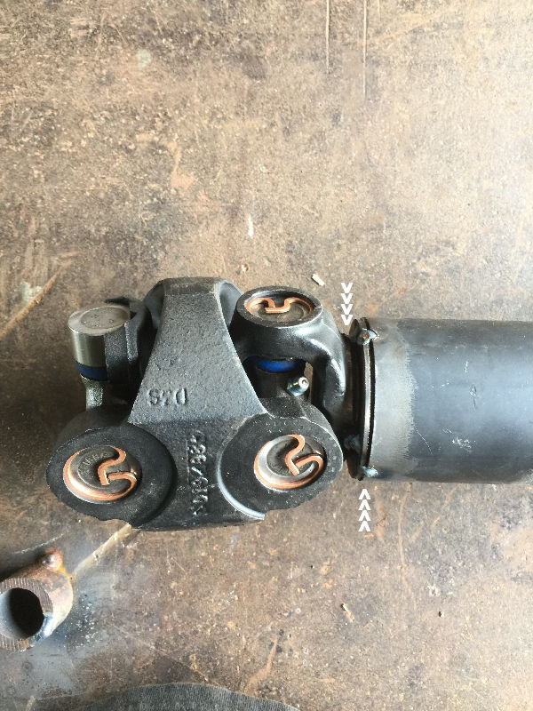
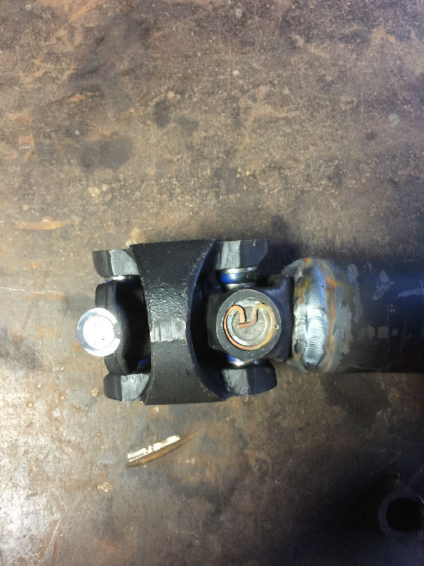
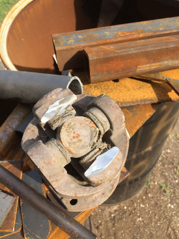 Picked up a front driveshaft front a 2003 Super Duty F-350. The pic shows that Ford Universal Joint. The part I cut off is the part that slips into the Ford driveshaft and is welded in place. We used the piece we cut off to make a flange to mate my Dodge Universal Joint to the Ford driveshaft. |
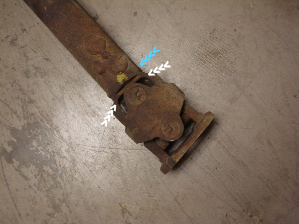 Using a cutting disk, we cut the weld at the driveshaft first. Take your time as you only want to cut into the weld and not the coupling below it. Once the driveshaft was removed, we cut the Universal Joint at the white arows. |
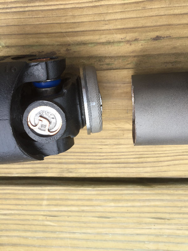
 This is the piece we cut off. The white arrows point to the area that went into the Ford driveshaft and had the weld around it. You do not want to do anything to this area as it has to slip back into the Ford drive shaft after we cut it to length later on. The area where the blue arrows point is what we will turn down. |
 We turned it down to get a nice flat wall. |
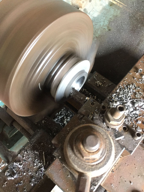 Then turned the inside down until the Durango's Universal Joint fit inside it. Once turned down, there will be a hole all the way through it. Then the Durango's Universal Joint will fit inside it and it will fit inside the Ford driveshaft. |
 The finished piece with the Durango's Universal Joint and the Ford driveshaft. |
 The piece fits over the Durango's Universal Joint |
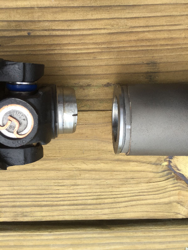 It also still fits back inside the Ford driveshaft. |
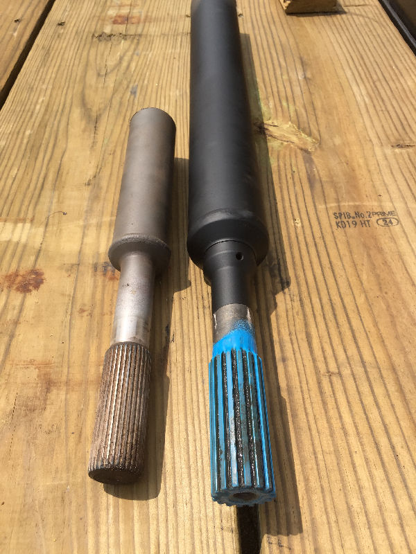 The Ford splines are a lot beefier |
 After determining the length we needed, we cut the Ford driveshaft. The using the flange, both were tack welded to gether. After determining the length we needed, we cut the Ford driveshaft. The using the flange, both were tack welded to gether. |
 |
 You have to weld both sides of the flange. |
 Everything welded out. |
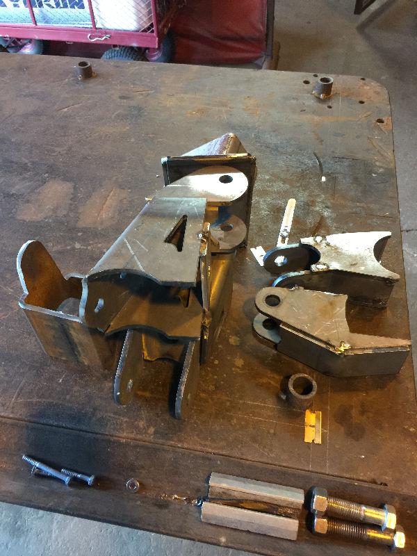
 I a Currie Antirock partial set up from a guy with another SAS Durango. He was parting it out. The arms were already bent to conform to the Durango frame. I had to purchase the Mounting Tube, Bushings, and Sway Bar from Summit Racing. The Sway Bar is 48", part # CE-9902J $187.97. The Mounting Tube is 48", 1.750" x 0.095", part # CE-9906H, $41.97. Bushings part # CE-9901D, $12.97 each. |
 We welded the brackets to hold the tube on the bumper guard brackets. Then welded the tube into the brackets. The Sway Bar runs inside the tube with the bushings on each end. Then the arms are bolted to the tube. |
 |
 White arrows point to the bushing. |
 |
 |
 White arrows point to the brackets we fabricated and drilled out for the tube. |
 |
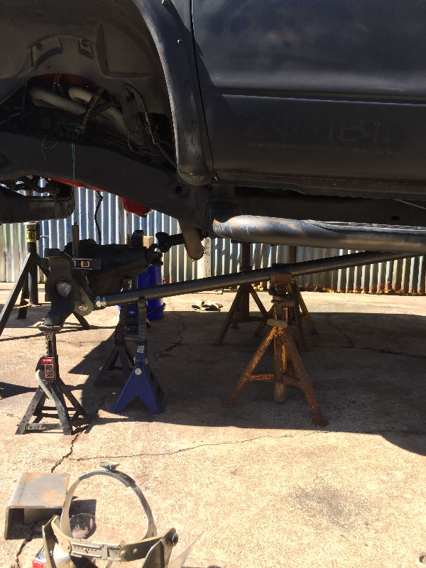
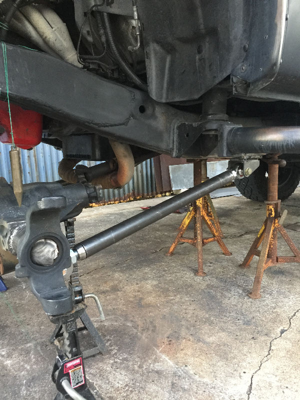
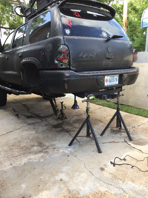
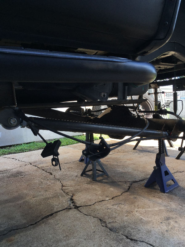
 Time to start on the rear suspension. |
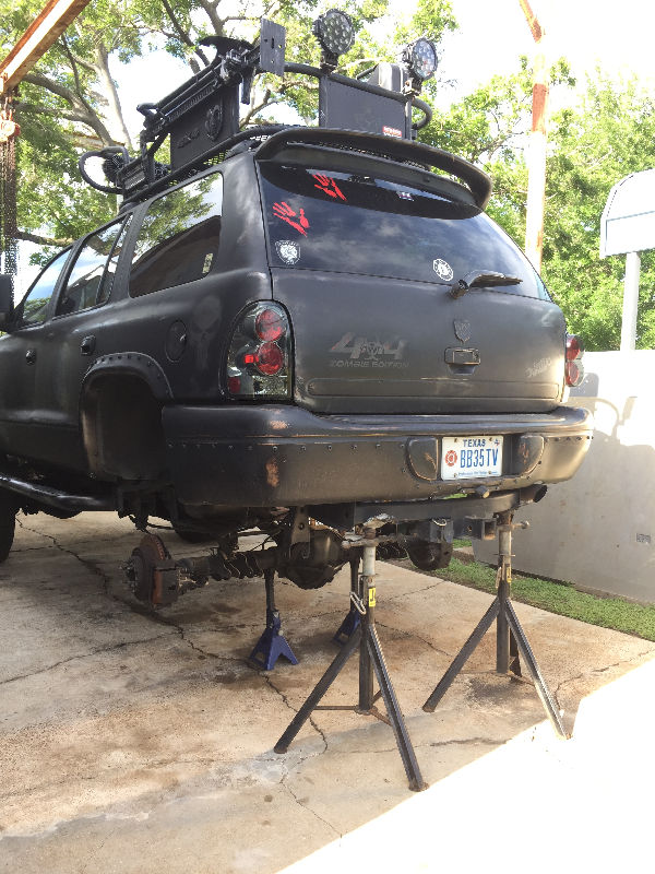 Unbolting and cutting everything out. |
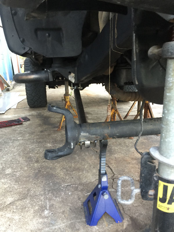
 After removal, we set the rear up to the ride hieght we wanted. |
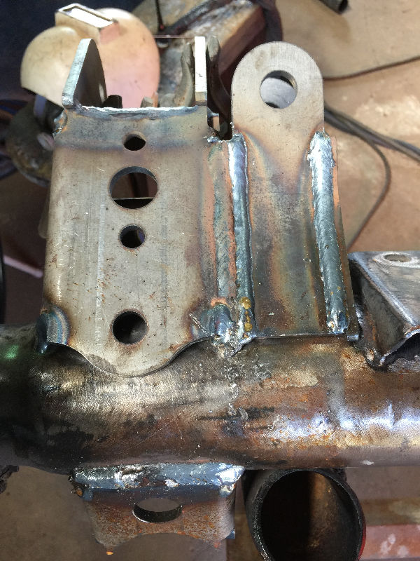
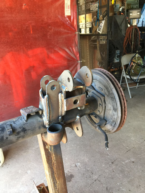
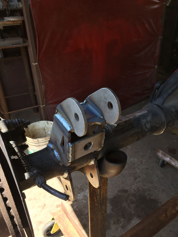
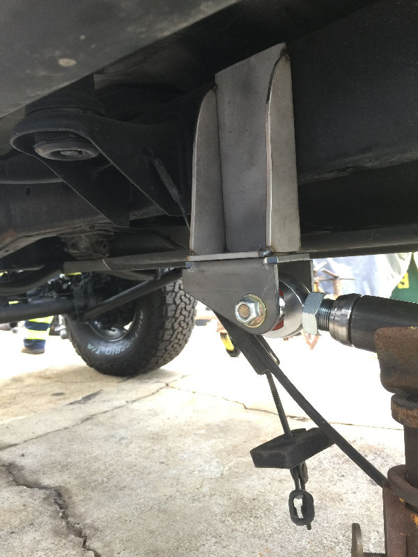 Fabricated the top mount to hold the bottom mount. Then tack welded it in place. The top bracket was later modified so the e-brake cable could pass through it. |
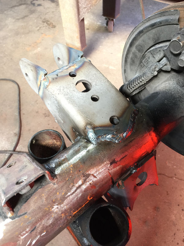
 Tack welded the axle mounts in place. |
 Just like the front, once we set the position on the axle, we marked the frame and used plumb bobs to keep it correct throughout the build. |
 |
 |
 Old spring mounts were cut off. The e-brake set up bolted to the one, so a new mount for it will be fabricated later on. |
 This shows why we couldn't do a triangulated set up due to the fuel tank. |
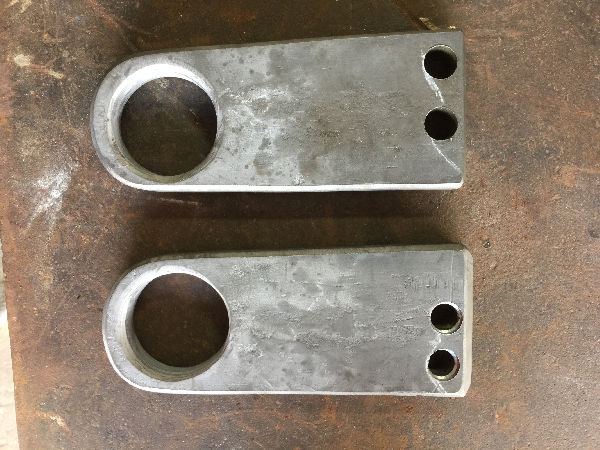
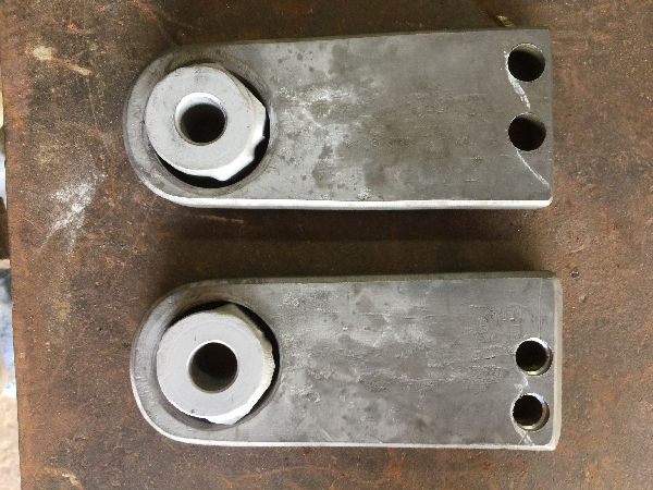
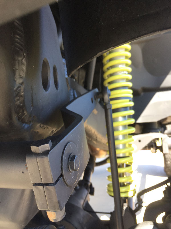
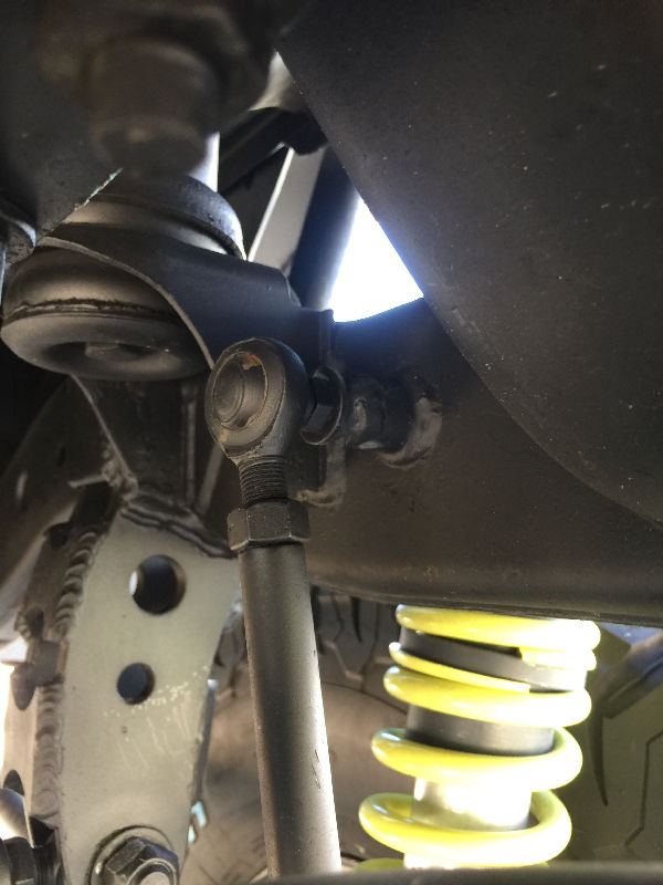
 Bottom links run straight with the frame. |
 The measurement between the bolt holes are 10 1/2". |
 Upper links were kept level with the ground at Durango ride height. |
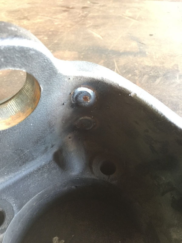
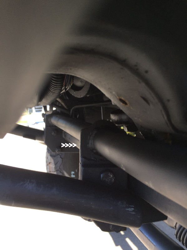
 White arrows point to where we modified the lower link bracket so the e-cable could pass through. |
 After everything was tacked up on the axle, it was removed for welding out. Remember, this is a slow process as you do not want to warp the axle. After everything was tacked up on the axle, it was removed for welding out. Remember, this is a slow process as you do not want to warp the axle. |
 |
 |
 |
|
|

|
|
|
|
|
|
|
|
|
|
|
|
|
|
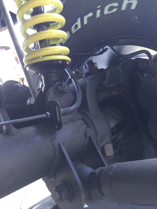
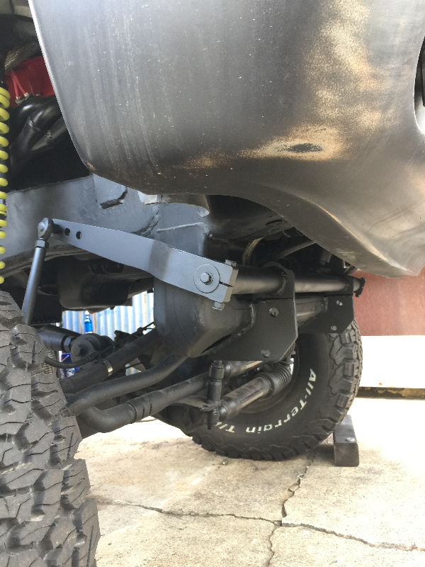
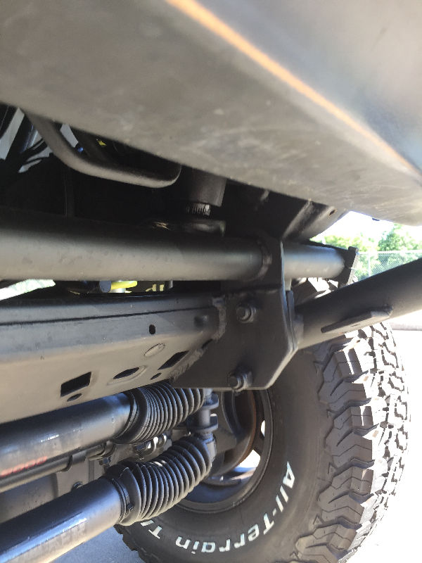
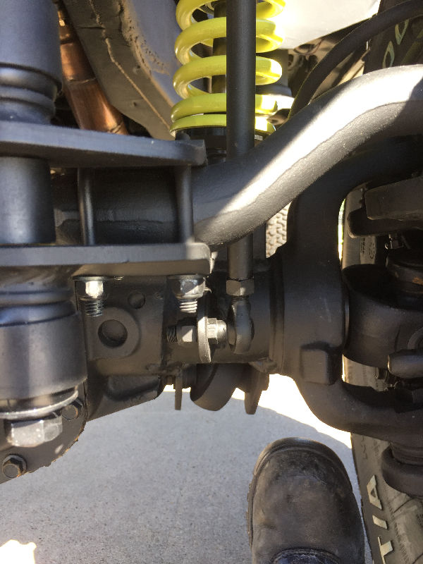
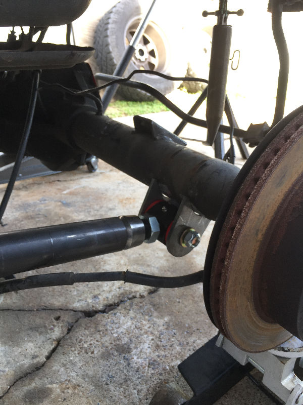
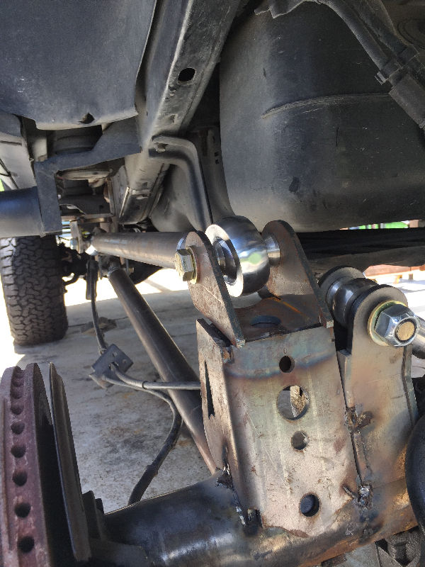
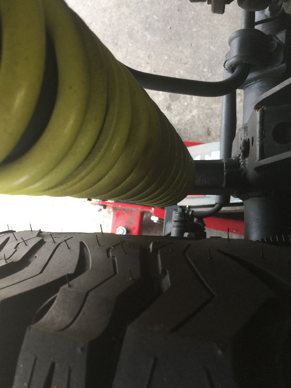
 Our first attempt at the rear Pan Hard Bar. Remember, this bar HAS to run opposite of the front Pan Hard Bar. So this one runs from passenger side frame to drivers side of axle. The front one runs from drivers side frame to passenger side axle. We had to re-fabricate the mounts on both ends of the Pan Hard Bar. It was at way to much of an angle. This bar needs to be as level as possible with the Durango at ride height. So at the frame, we fabricated a new longer mount to mount the Rod End under the frame. Then at the axle, we fabricated anew mount that fit over the existing mount. |
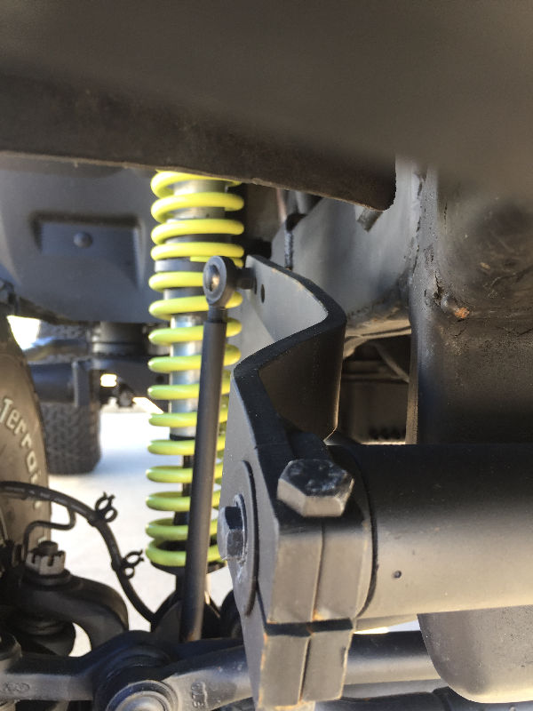
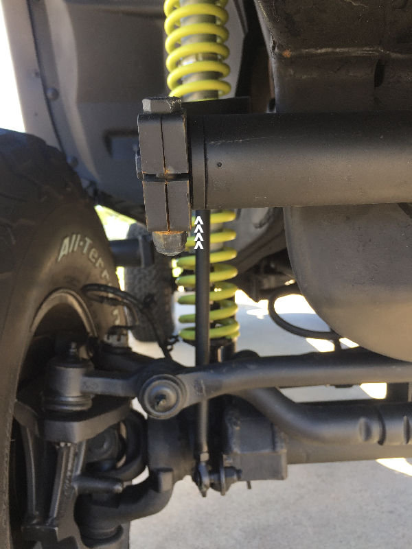
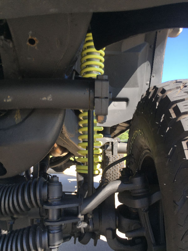
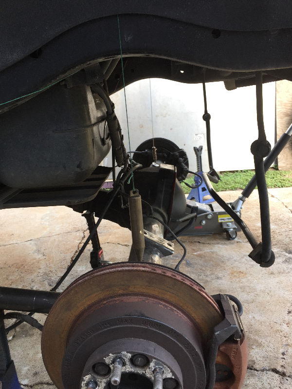
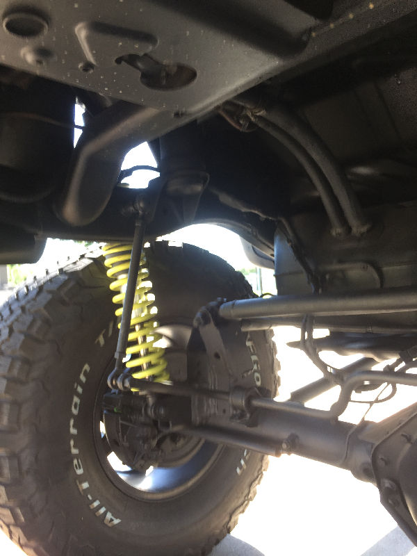
 Finding a way to mount the Coilovers proved to be difficult. The Pan Hard Bar and Sway Bar kept me from installing the upper end inside the frame. Also, you want the lower end as close to the axle ends as possible. Where the lower end is sitting now, is as close the the axle end as I could get it. So we fabricated mounts to weld onto the link mounts. Remember, I chosed to do this project using my existing rear axle and not a Dana 60. The Dana 60 would have given me more room to mount the Coilovers easier. |
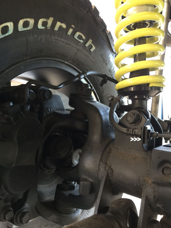
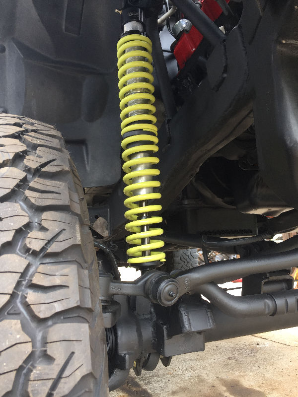
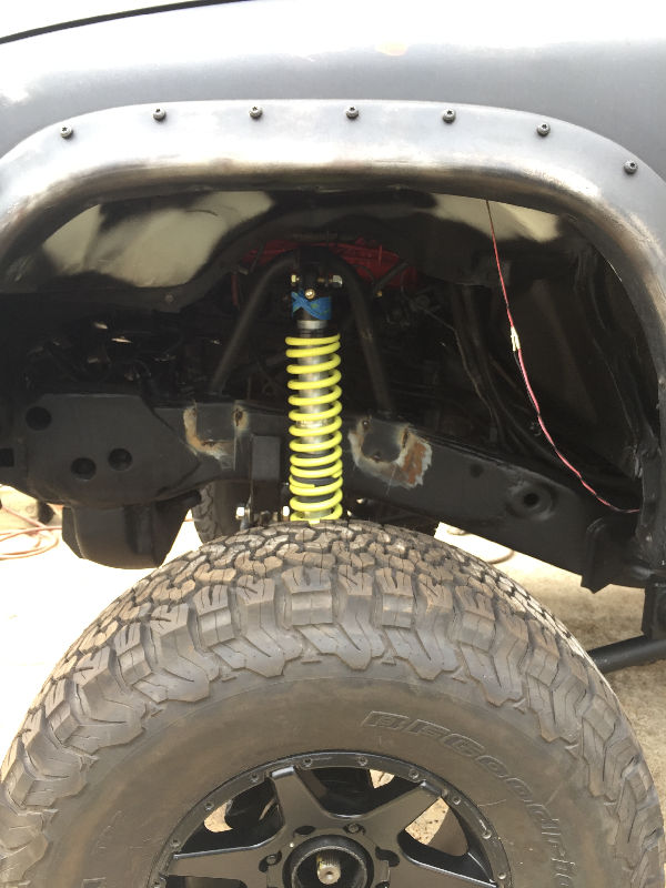
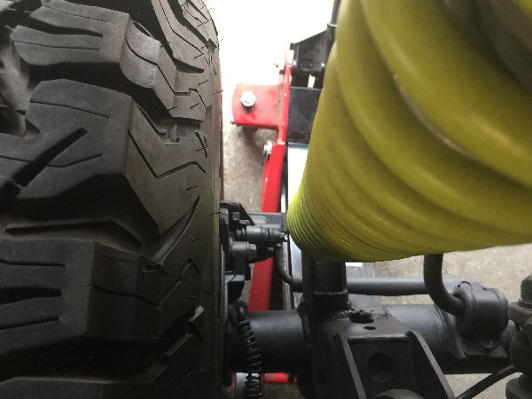
 This is when we found out that I didn't get the right rims. These rims have zero offset, which left me with very little space between the coils and tires. We chose to mount the upper ends slightly back, off center, hoping the tire would not eat into the coils when flexing. |
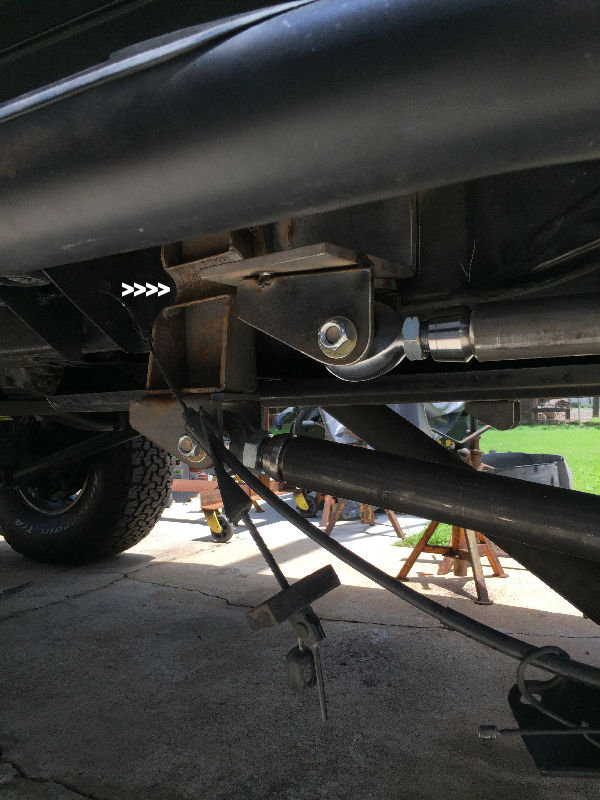
 You can see the two new Pan Hard mounts, plus that the bar is now closer to being level. |
 |
 Welding out the Coilover and Pan Hard Bar mounts. |
 |
 Sitting on its own. |
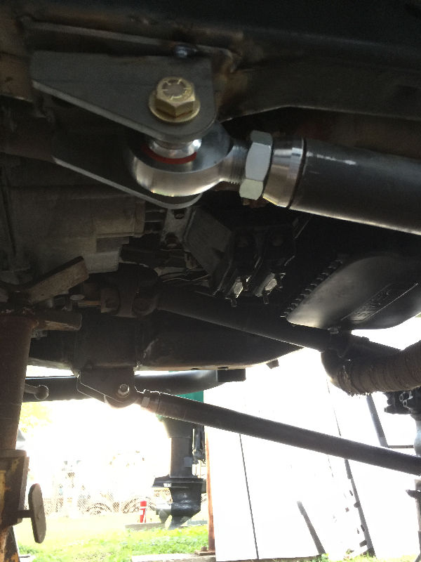
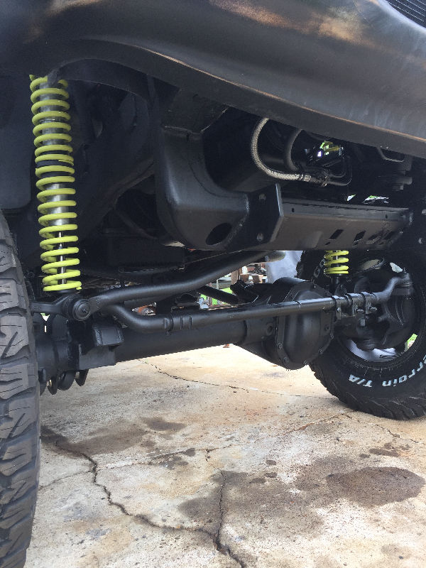
 We used the stock Sway Bar since it is set up for the axle already. We had to add the longer arms with the heim joints. The arms are adjustable. |
 |
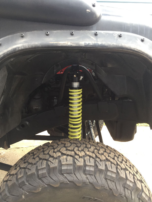
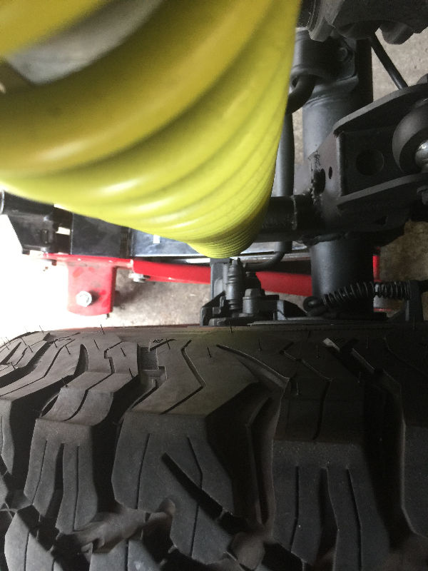
 This shows how close the rear tires and coilovers are. I went back to discount and showed them once the Durango was drivable. I did order the rims with an offset and the computer showed that. So they gave me a fulll refund on them and ordered the right rims. |
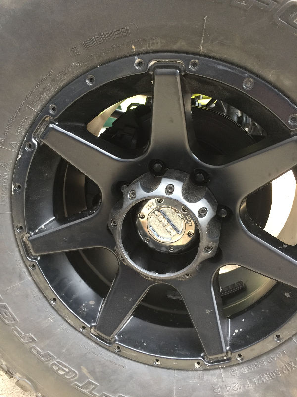
 Old rims |
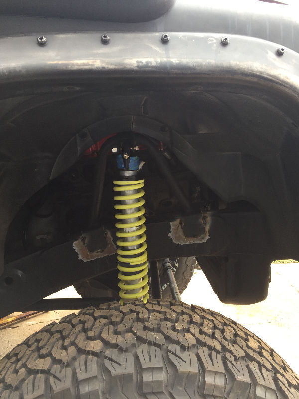
 New rims |
 Now I have plenty of room between coilovers and tires. |
 |
 New rims are Moto Metal 962 17 x 10 |
 |
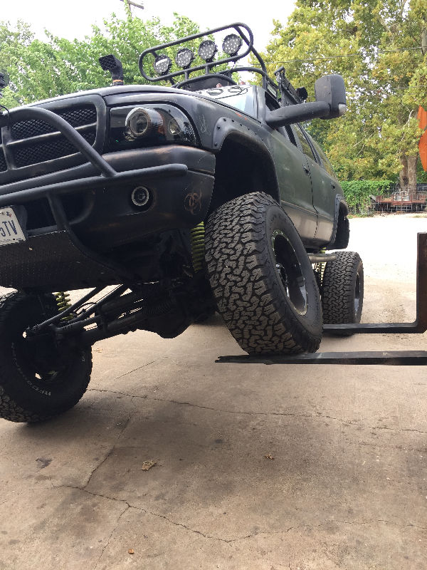 After flexing it with a forklift, nothing rubs, hits and the rear coilovers do not even come close to the tires. |
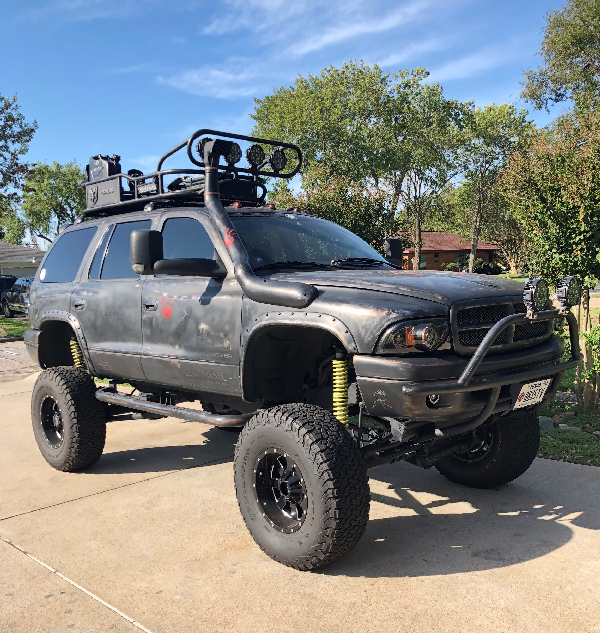
 With my Sway Bars front and rear adjusted properly, I haven't had to put limiting straps or bumps stops on it. Though those are coming soon. That way I can disconnect the sway bar for more articulation. |
 |
 |
|
|
 |